Principle
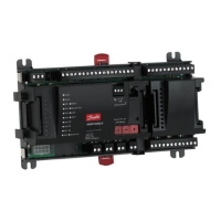
This page describes the setups that are to be installed in the
monitoring unit.
The points are detailed briey so that the list can be used as a
checklist.
The monitoring unit is set up once each point has been reviewed.
Configuration
Point no.
in display
Name Type of connection Place of
connection
Priority of alarm Note
Tempe-
rature
Di
(on/
off)
Ai
(ana-
log)
Pow-
er
meter
Power
meter
log
Gas-
detector
Controller Wireless Terminal Address High Me-
dium
Low Log
only
1 xxxx A x 1-16 x
2 xxxx B x 1-16 x
3 xxxx C x 1-16 x
4 xxxx D x 1-2 x 1 or 2 only
5 xxxx E x 1-65 x
6 xxxx F x 1-xxx x
7 xxxx G x m2+:
1-16
1-7 x From m2+ via data
communication
8 xxxx H x x TCP/IP 12-999 Static IP in AK-W_
Static/dynamic in
AK-SM 350
9 xxxx J x Load/store data
from Power meter
If you require help setting up individual points, you will find a
more detailed explanation in the next section – The functions’
mode of operation.
Then continue by:
2. Pressing the button for the main menu
3. Selecting "Service Setup" at the bottom of the display
4. Go through all the functions in "Basic setup". In one of the func-
tions, the network will be scanned, which allows the monitoring
unit to recognise all the connected units on the data communi-
cation. Do not forget that the controllers and the wireless unit
must have an address set, or to check that the power is turned
on before the scan function is enabled.
5. Select Point setup
6. Set all points. Use data from a table like the one above. Some of
the readings will have two alarm limits. Different alarm priorities
can be set for each one.
7. Create a table of the alarm activities. See the table on the right.
8. Set up the alarm function
a. Set the general functions first
b. Then set how an alarm should be handled/routed (i.e. what
will be enabled)
c. And finally, set up the activities chosen (e.g. addresses of the
alarm destinations)
9. Check that the alarms can be sent properly
a. Set the function "Test alarm priority" to "high"
b. Enable the function "Test alarm"
c. Check that the alarm is received
d. Repeat this check for the other alarm priorities
e. Repeat this check until all the destinations have been tested
to see if they can receive alarms.
Procedure
1. Create an overview of all the connections.
Decide where they will be connected.
Decide the alarm priority for the reading.
The table below shows some examples of the various possibilities.
Table of alarm activities (example)
(Referred to in point 7 and utilised in point 8b)
Route 1
Time Alarm
priority
Alarm activity
Remote
no.
Relay Buzzer SMS
Primary alarm destination
Day High 1 x
Medium 1
Low 1
Night High 2
Medium 2
Low -
Alternate destination (if the link to the primary destination fails)
Day High
Medium
Low
Night High
Medium
Low
Copy destination
Day High
Medium
Low
Night High
Medium
Low
 Loading...