7-06 Speed PID Lowpass Filter Time
Range: Function:
10.0
ms
*
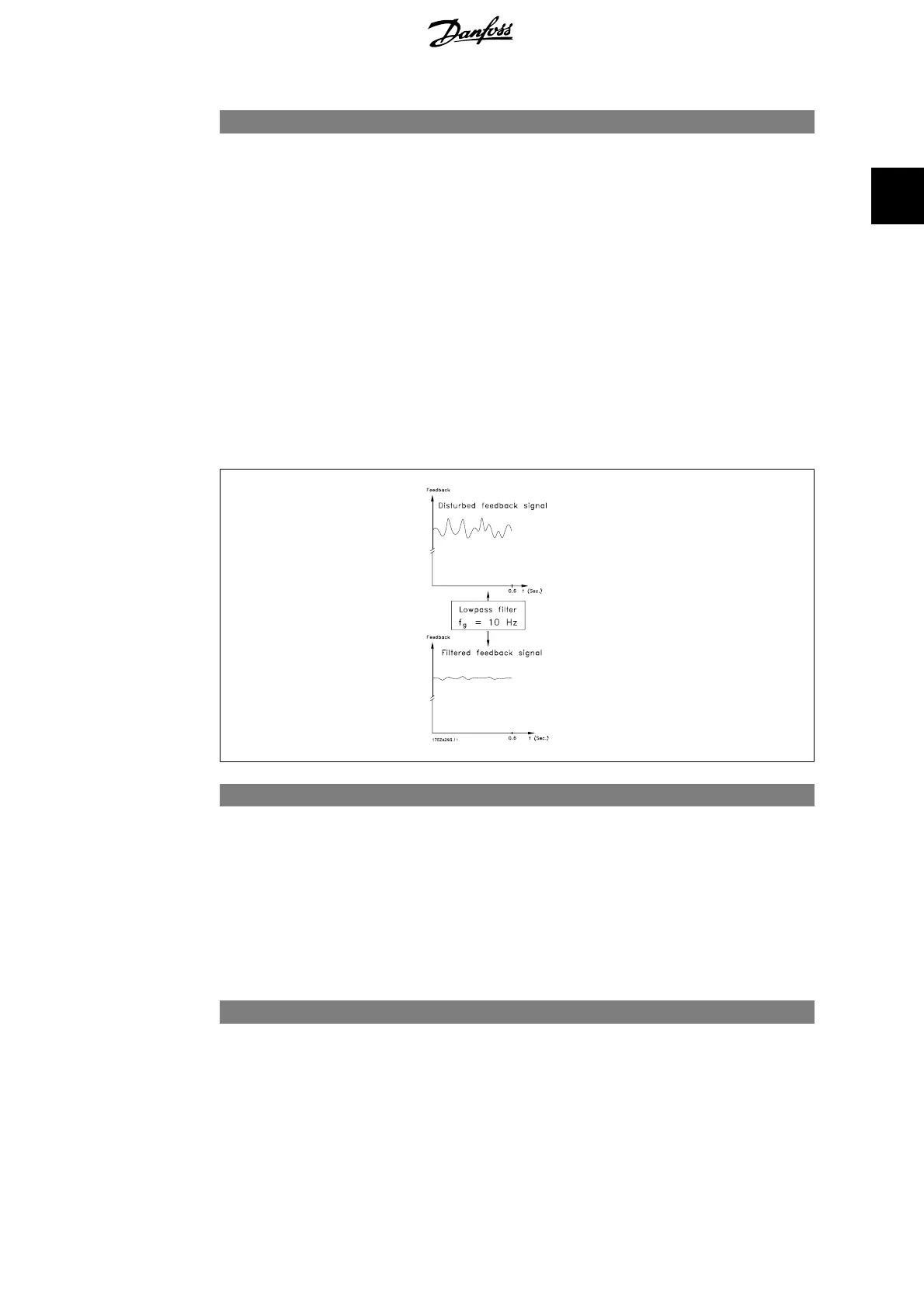
[1.0 - 100.0 ms] Set a time constant for the speed control low-pass filter. The
low-pass filter improves steady-state performance and damp-
ens oscillations on the feedback signal. This is an advantage if
there is a great amount on noise in the system, see illustration
below. For example, if a time constant (τ) of 100 ms is pro-
grammed, the cut-off frequency for the low-pass filter will be
1/0.1= 10 RAD/sec., corresponding to (10/2 x p) = 1.6 Hz. The
PID regulator only regulates a feedback signal that varies by a
frequency of less than 1.6 Hz. If the feedback signal varies by
a higher frequency than 1.6 Hz, the PID regulator does not re-
act.
Note that severe filtering can be detrimental to dynamic per-
formance.
This parameter is used with par. 1-00
Speed closed loop
[1] and
Torque
[2] control.
7-08 Speed PID Feed Forward Factor
Range: Function:
0%
*
[0 - 500%] The reference signal bypasses the speed controller by the
amount specified. This feature increases the dynamic perform-
ance of the speed control loop.
2.10.3. 7-2* Process Ctrl. Feedb.
Select the feedback sources for the Process PID Control, and how this feedback should be handled.
7-20 Process CL Feedback 1 Source
Option: Function:
The effective feedback signal is made up of the sum of up to
two different input signals.
Select which frequency converter input should be treated as the
source of the first of these signals. The second input signal is
defined in par. 7-22.
FC 300 Programming Guide 2. How to Programme
MG.33.M2.02 - VLT
®
is a registered Danfoss trademark
123
2

 Loading...


