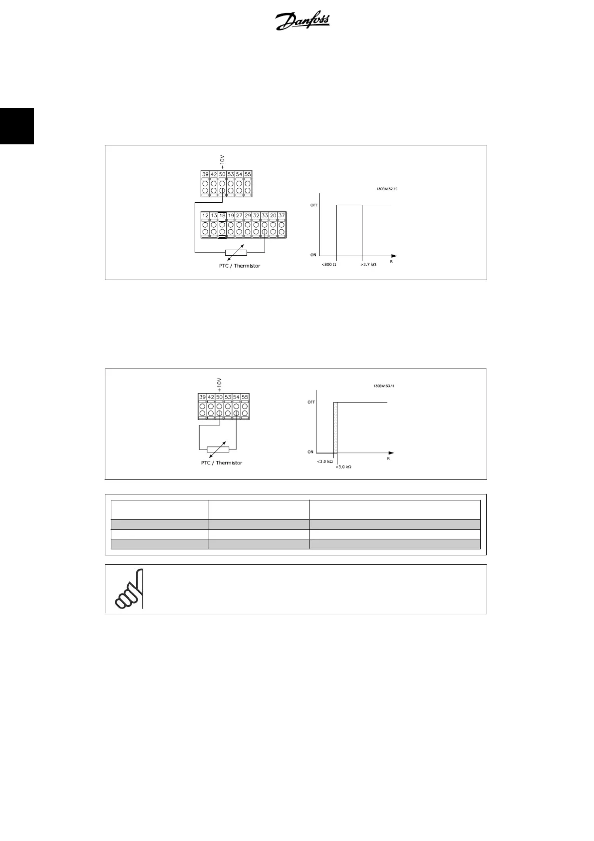
Using a digital input and 10 V as power supply:
Example: The frequency converter trips when the motor temperature is too high.
Parameter set-up:
Set Par. 1-90
Motor Thermal Protection
to
Thermistor Trip
[2]
Set Par. 1-93
Thermistor Source
to
Digital Input
[6]
Using an analog input and 10 V as power supply:
Example: The frequency converter trips when the motor temperature is too high.
Parameter set-up:
Set Par. 1-90
Motor Thermal Protection
to
Thermistor Trip
[2]
Set Par. 1-93
Thermistor Source
to
Analog Input 54
[2]
Input
Digital/analog
Supply Voltage
Volt
Threshold
Cut-out Values
Digital 24 V < 6.6 kΩ - > 10.8 kΩ
Digital 10 V < 800Ω - > 2.7 kΩ
Analog 10 V < 3.0 kΩ - > 3.0 kΩ
NB!
Check that the chosen supply voltage follows the specification of the used thermistor
element.
Select
ETR Warning 1-4
, to activate a warning on the display when the motor is overloaded.
Select
ETR Trip 1-4
to trip the frequency converter when the motor is overloaded.
Programme a warning signal via one of the digital outputs. The signal appears in the event of a
warning and if the frequency converter trips (thermal warning).
ETR (Electronic Terminal Relay) functions 1-4 will calculate the load when the set-up where they
were selected is active. For example ETR starts calculating when setup 3 is selected. For the North
American market: The ETR functions provide class 20 motor overload protection in accordance
with NEC.
2. How to Programme FC 300 Programming Guide
60
MG.33.M2.02 - VLT
®
is a registered Danfoss trademark
2
 Loading...


