Reset or replace a
Danfoss Icon™
Master Controller
24V
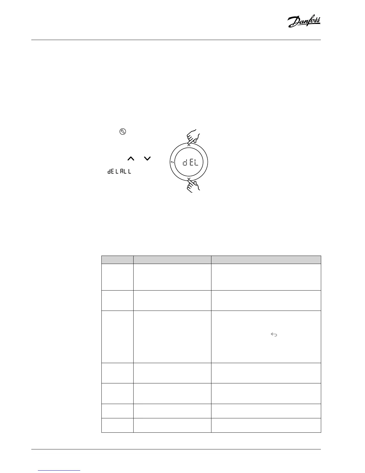
Factory resetting of Danfoss Icon™ Master
Controller 24V
1. Press to select UNINSTALL
mode.
2. On the Danfoss Icon™
Master Controller 24V, press
and hold and for 3
seconds until the display says
.
3. Press OK. All settings on
Master Controller are reset to
factory settings.
Note! Individual room thermostats must be reset
locally, see chapter “Removing a thermostat”.
Replacing a defective Danfoss Icon™ Master
Controller 24V
1. Remove all thermostats and other units from
the system by following the procedure for
factory resetting.
2. Make a note of how all wires are connected to
the Danfoss Icon™ Master Controller 24V.
3. Remove wiring to Danfoss Icon™ Master
Controller 24V.
4. Mount the new Danfoss Icon™ Master Controller
24V and reconnect all wires to the same position
as on the replaced Master Controller.
5. Set up system again as described in chapter
“Setting up the system”.
OK
Trouble shooting
If an error is detected, an alarm code will be displayed either on the Danfoss Icon™ Master Controller
24V or on the thermostat.
Alarm code Problem Solution
Er03 You have set-up a cooling applica-
tion that requires a reference room
thermostat to be appointed.
Please go to the thermostat in the desired
reference room and enter the thermostat installer
menu. Set thermostat to ON in ME.6 ”reference
room thermostat”.
Er05 Communication lost to Radio
Module.
Please check that the cable is properly connected
in the Radio Module and Danfoss Icon™ Master
Controller 24V.
Er06 Communication lost to room
thermostat.
Identify the room thermostat by looking at the
ashing outputs on the Danfoss Icon™ Master
Controller 24V, or look at the thermostats. Wake
up thermostat, then press on the thermostat.
Failing thermostat will say “NET ERR”.
Replace batteries on room thermostat and perform
a network test (activate NET TEST in menu on room
thermostat).
Er07 Communication lost to Slave
Controller.
If wireless, check Radio Module connection to
Danfoss Icon™ Master Controller 24V. If wired
system, check the wire connecting the controllers.
Er08 Communication lost from Slave to
Master Controller.
If wireless, check Radio Module connection to
Danfoss Icon™ Master Controller 24V. If wired
system, check the wire connecting the controllers.
Er10 Communication lost to Repeater. Check that the repeater is plugged into outlet / has
not been removed and outlet is ON.
Er11 Communication lost to Expansion
Module.
Check that Expansion Module is slidded fully into
place.
The potential free relay is activated on all Master
Controllers when heat is demanded on either
Master Controller.
SLA TYPA: Pump is activated on Danfoss Icon™
Master Controller 24V when heat is demanded on
either Master or Slave(s).
SLA TYPB: Pump relay is only activated on the
Danfoss Icon™ Controller 24V to which the
thermostat with heat demand is assigned.
Slave type denition
10 | © Danfoss | FEC | 2019.02
 Loading...