Connecting more
Danfoss Icon™
Master Controllers in
a system
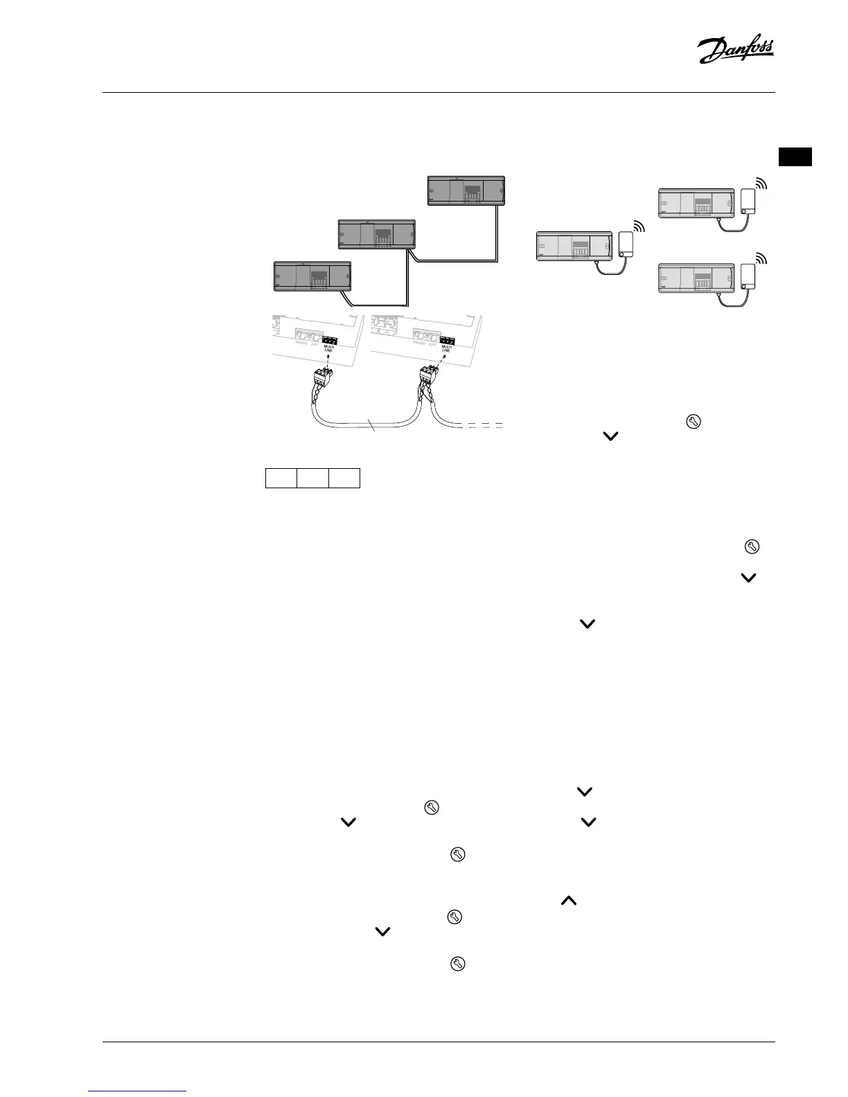
If wired system
Connect up to three Danfoss Icon™ Master
Controller 24V to each other with a 4-wire twisted
pairs cable and the supplied connector.
Cable pin out
1 2 3
1. GND
2. COM A
3. COM B
If wireless system
Wireless connection of up to three Danfoss Icon™
Master Controllers 24V requires a Radio Module
with each Master / Slave.
Connecting procedure for multiple Danfoss
Icon™ Controllers in a system
On System Master
1. Install all thermostats and thermal actuators as
described in the Quick Guide D2 to D6.
2. Perform network test. Press to select TEST
and press to choose NET TEST. Conrm
witk OK (Quick Guide E7 and E8).
Pairing Master and Slave
Note! Slave Controllers must be assigned as System
Slaves before assigning outputs and thermostats to
them.
1. On the selected system master, press to
select INSTALL mode.
2. On the system slave, press and hold for
1,5 sec. The display now toggles between
SLA TYPA and SLA TYPB.
3. Press to choose between the two slave
types and conrm with OK. See “Slave type
denition” on the next page.
4. Repeat step 1 – 3 to assign a 2
nd
Slave Controller
to the system (max. two slaves are permitted).
NET TEST on System Slave
1. Install all thermostats and actuators as
described in the Quick Guide D2 to D6.
2. Perform Network test. Press to select TEST
and press to choose NET TEST. Conrm
with OK (Quick Guide E7 and E8).
3. After completing the TEST press to select
RUN mode and press OK (Quick Guide E9).
APP TEST on System Master
1. Perform application test. Press to select
TEST and press to choose APP TEST.
Conrm with OK (Quick Guide E7 and E8).
2. After completing the TEST press to select
RUN mode and press OK (Quick Guide E9).
Note! If an Expansion Module is added to the system,
it must be installed on the Master Controller.
Changing Slave type
1. On Danfoss Icon™ Slave Controller press and
hold for 1.5 sec. The display now toggles
between SLA TYPA and SLA TYPB.
2. Press to choose between the two slave
types and conrm with OK. See “Slave type
denition” for more information.
LINK test on Slave (between Master and Slave)
Press for 1.5 sec. The display shows inclusion
pattern while making the LINK test. When done, the
display shows the number of packages recieved in
percentage.
Test procedures for
multiple Danfoss
Icon™ Controllers in a
system
VIMCG30F | 088N3678 | 9
© Danfoss | FEC | 2019.02
 Loading...