Upon rst installation the system is congured as
a standard oor heating system. In this application
the circulation pump output and the potential free
relay are both activated when there is a heat de-
mand.
Both the boiler relay and the pump output has a
delay of 180 seconds in this application to ensure
there is ow through the circuits before the boiler
is activated.
The use of mixing shunt, connection of circulation
pump to Danfoss Icon™ Master Controller 24V and
use of boiler relay is optional, depending on appli-
cation and available components.
To congure the Danfoss Icon™ Master
Controller 24V system for other applications an
Expansion Module (code no. 088U1100) is required.
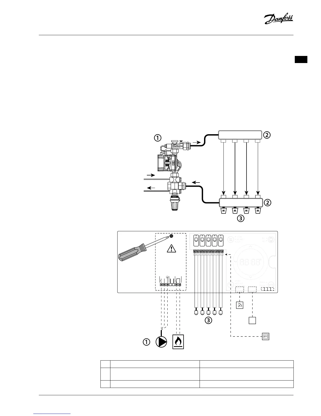
Application
Application, Basic
• 2-pipe system
• Mixing shunt (optional)
Parts list
1 1 pc. Danfoss FHM-Cx mixing shunt (optional) Part no. 088U0093/0094/0096
2 1 set Danfoss Manifold Part no. 088U05xx (FHF), 088U06xx (BasicPlus) or
088U07xx (SSM)
3 x pcs. TWA-A 24 V thermal actuators Part no. 088H3110 (NC), 088H3111 (NO)
 Loading...