4.15 SCR DC Bus Bar - TTS300/TGS230
TheSCRDCBusBarspasstheDCvoltagefromtheoutputoftheSCRstotheDCCapacitorBusBarAssembly.This
proceduredoesnotshowtheremovaloftheSoftStartsinceitisnotrequired.However,ifextraroomisdesired,the
SoftStartcanberemovedtoprovidebetteraccesstothefastenersthatsecuretheSCRDCBusBarstotheDC
CapacitorBusBarAssembly.
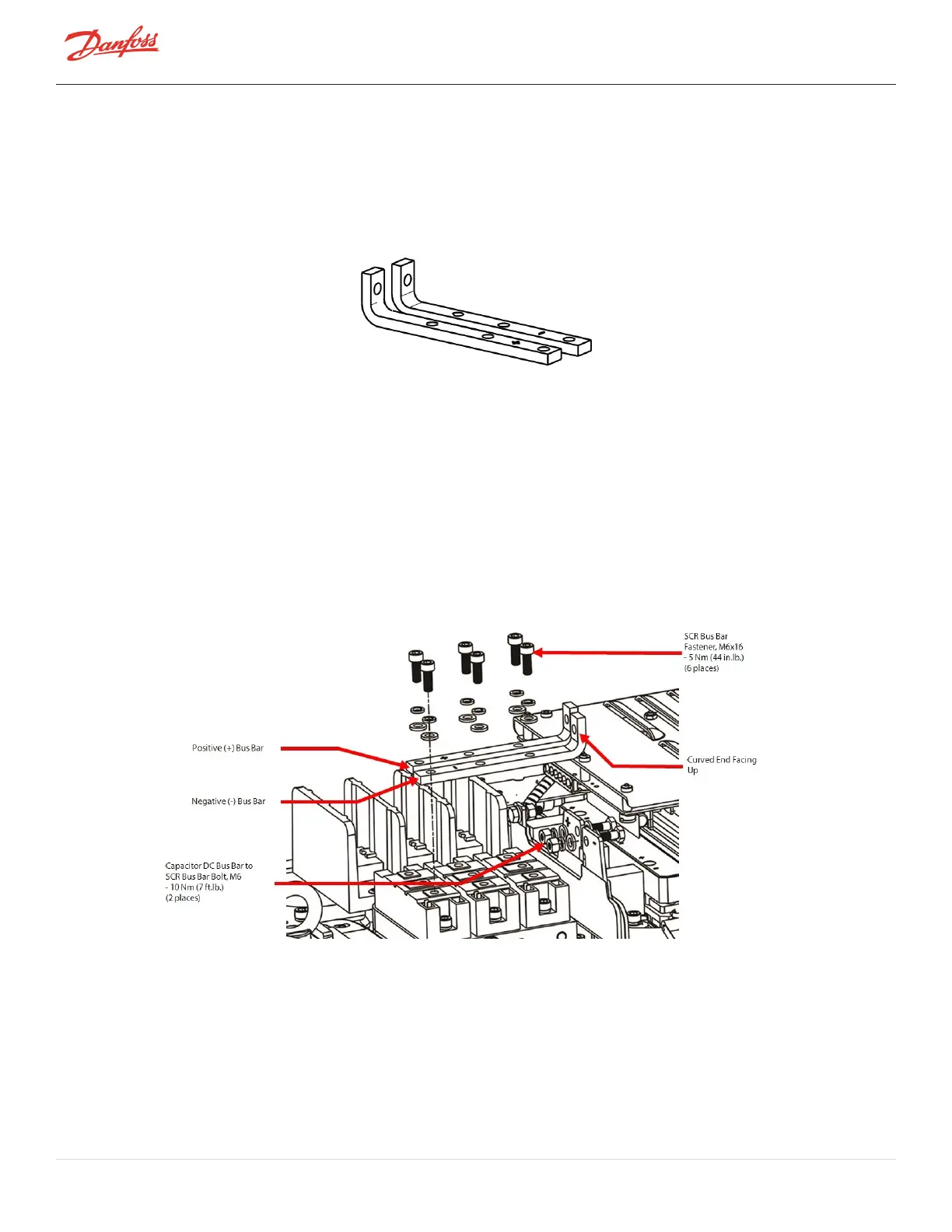
Figure 4-115 SCR DC Bus Bars
4.15.1 SCR DC Bus Bar Removal and Installation
4.15.1.1 SCR DC Bus Bar Removal - TTS300/TGS230
1. IsolatethecompressorpowerasdescribedinSection1.8ElectricalIsolationonpage22.
2. Usinga10mmwrench/socket,removetheboltsthatsecurethe(+)and(-)SCRDCBusBarstotheDC
CapacitorBusBars.RefertoFigure4-116SCRDCBusBarRemoval-TTS300/TGS230forthisandthe
nexttwo(2)steps.
3. Removethesix(6)M6x16fastenersthatsecurethe(+)and(-)SCRDCBusBarstotheSCRs.
4. RemovetheSCRDCBusBars.
Figure 4-116 SCR DC Bus Bar Removal - TTS300/TGS230
4.15.1.2 SCR DC Bus Bar Installation - TTS300/TGS230
1. PlacethenegativebusbarontheSCRs.ThenegativebusbarshouldbenexttotheSCRGatepins
(alignedwiththeholesidentifiedas#3ontheSCRs).RefertoFigure4-117SCRDCBusBartoSCR
Alignmentonpage127forthisandthefollowingstep.
Page 126 of 294 - M-SV-001-EN Rev. H 1/23/2023