4.19.4 SCR Cooling Manifold Specific Installation Steps - TTS300/TGS230
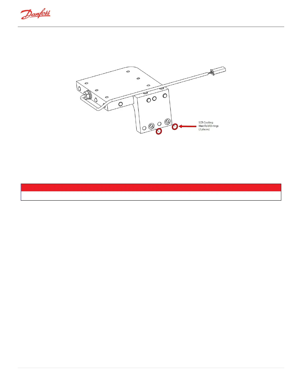
1. ApplyO-LubetotheO-ringsandinstallthemintotheSCRcoolingmanifold.RefertoFigure4-172SCR
ManifoldO-ringInstallation-TTS300/TGS230.
Figure 4-172 SCR Manifold O-ring Installation - TTS300/TGS230
2. InstalltheSCRCoolingManifoldtotheInverterCoolingManifoldusingthetwo(2)M6x20fasteners.
Torqueto7Nm(62in.lb.).
3. SecuretheinsulationontothebacksideoftheSCRCoolingManifold.
4. InstalltheInverter.RefertoSection4.22.6.3CompressorSpecificInverterInstallationSteps-
TTS300/TGS230onpage185.
NOTE
Itisrecommendedthatthenewfastenerssuppliedwiththekitbeusedtoensurepropertorqueisobtained.
5. IftheSCRswereremovedpreviously,installtheSCRstotheSCRcoolingmanifold.TorquetheSCR
fastenersto5Nm(44in.lb.).RefertoSection4.18.3.4SCRInstallation-TTS300/TGS230onpage153.
6. InstalltheDCBusBarandCapacitorAssembly.RefertoSection4.21.4.3DCCapacitorBusBarAssembly
Installation-TTS300/TGS230onpage174.
7. InstalltheTerminalBlockandtorquetheM5x15fastenersto3Nm(27in.lb.).RefertoSection4.11.23-
PhaseMainVoltageInputTerminalBlockRemovalandInstallationonpage102.
8. InstalltheCapacitorCover.RefertoSection4.1.4.1CapacitorCoverRemovalandInstallationonpage
55.
9. Installthefuseassemblies.Torquethesix(6)fastenersto4Nm(35in.lb.).
10. InstallthemainsinputcablestotheTerminalBlockandtorqueto20Nm(15ft.lb.).
11. Leaktestandevacuatethecompressorinaccordancewithstandardindustrypractices.
12. ContinuetoSection4.19.6SCRCoolingManifoldGeneralInstallationStepsonpage162.
4.19.5 SCR Cooling Manifold Specific Installation Steps - TTS/TGS/TTH/TGH (Except TTS300/TGS230)
1. CleantheO-ringgrooveontopoftheInverterCoolingManifoldwithalint-freecloth.
2. ApplyO-LubetoanewInverterHeatSinkO-ringandplaceintheO-ringgroveintheInverterHeatSink
Plateandinstall.RefertoFigure4-173InverterHeatSinkPlateO-ringInstallation-TTS/TGS/TTH/TGH
(ExceptTTS300/TGS230)onpage161.
Page 160 of 294 - M-SV-001-EN Rev. H 1/23/2023