4.31.4 Cavity Temperature Sensor Removal and Installation
4.31.4.1 Cavity Temperature Sensor Removal
1. Isolatecompressorpower.
2. WaitfortheLEDsontheBackplanetoturnoff.
3. Isolatethecompressorandrecovertherefrigerantaccordingtoindustrystandards.RefertoSection3.1
RefrigerantContainmentonpage41.
4. RemovetheServiceSideCover.RefertoSection4.1.3.1ServiceSideCoverRemovalandInstallationon
page54.
5. VerifytheLEDsontheBackplanehaveturnedoff.
6. RemovetheSerialDriver.RefertoSection4.26.4SerialDriverRemovalandInstallationonpage218.
7. RemovetheBMCC.Referto4.27BMCConpage220.
8. RemovethePWM.Referto4.28.4PWMRemovalandInstallationonpage228.
9. RemovetheBackplane.4.25.3BackplaneRemovalandInstallationonpage215.
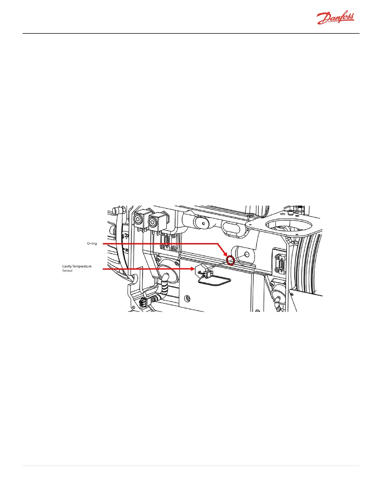
10. Usinga15/16”wrenchorslottedsocket,removetheMotorCavitySensor.
Figure 4-269 Cavity Temperature Sensor Removal
4.31.4.2 Cavity Temperature Sensor Installation
1. Cleanthematingsurfacewithalint-freecloth.Inspectthesealingareaforanydamage.
2. LubricatetheO-ringandinstallontothegrooveinthesensorhead.
3. Insertthesensorandengagethefirstfewthreadsbyhand.
4. Tightenthesensorto13Nm(10ft.lb.).
5. Leaktestandevacuateinaccordancewithstandardindustrypractices.
6. InstalltheBackplane.RefertoSection4.25.3BackplaneRemovalandInstallationonpage215.
7. InstallthePWM.RefertoSection4.28.4PWMRemovalandInstallationonpage228.
8. InstalltheBMCC.RefertoSection4.27BMCConpage220.
9. InstalltheSerialDriver.Referto4.26.4SerialDriverRemovalandInstallationonpage218.
10. InstalltheServiceSideCover.RefertoSection4.1.3.1ServiceSideCoverRemovalandInstallationon
page54.
M-SV-001-EN Rev. H-1/23/2023 Page 243 of 294