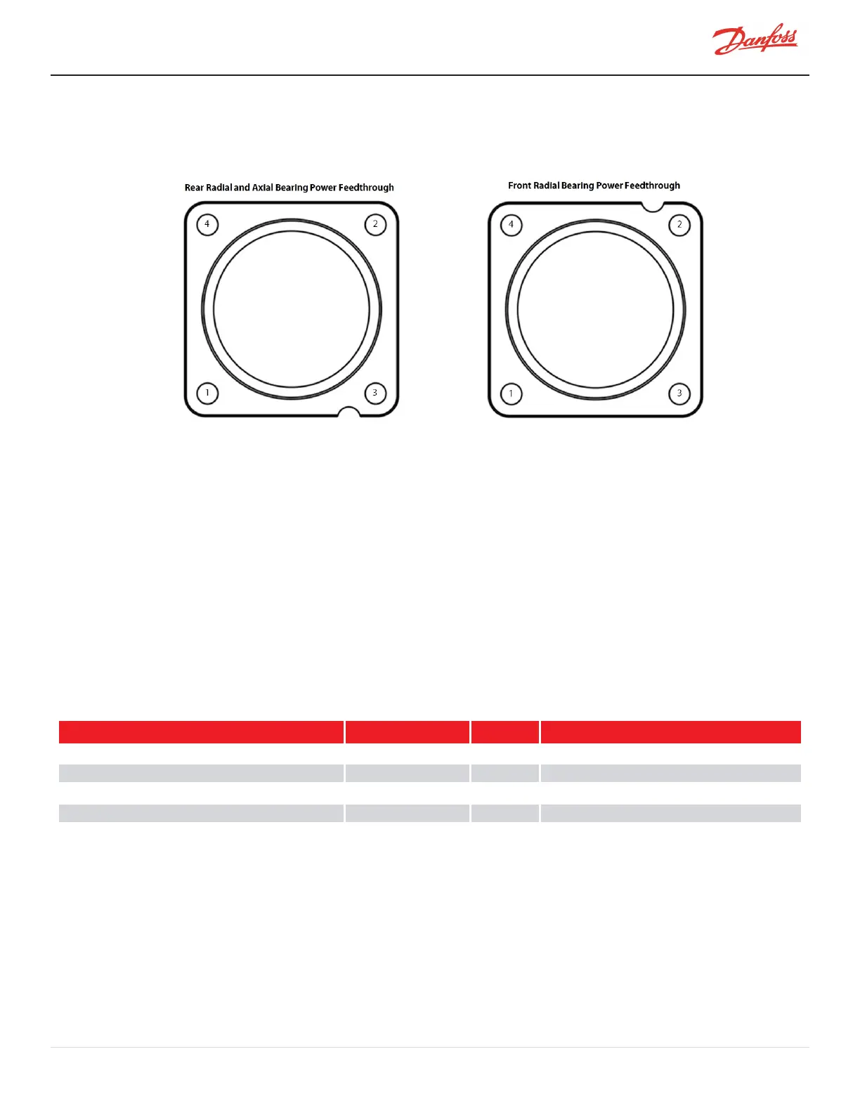
5. Finger-tightenthefour(4)M5x16fastenersandthentorqueinacrisscrosspatternto3Nm(27in.lb.)
andthentoafinaltorqueof5Nm(44in.lb.).RefertoFigure4-261BearingPowerFeedthroughTorque
Sequence.
Figure 4-261 Bearing Power Feedthrough Torque Sequence
6. Leaktestandevacuateinaccordancewithstandardindustrypractices.
7. CarefullyinstallthePWM.RefertoSection4.28.4PWMRemovalandInstallationonpage228.
8. Plugthecableharnessesbackintothe4-pinfeedthroughand6-pinfeedthrough.
9. Carefully,installtheBMCC.RefertoSection4.27BMCConpage220.
10. Carefully,installtheSerialDriver.RefertoSection4.26.4SerialDriverRemovalandInstallationonpage
218.
11. InstalltheServiceSideCover.RefertoSection4.1.3.1ServiceSideCoverRemovalandInstallationon
page54.
12. Returnthecompressortonormaloperation.
4.29.4.3 Magnetic Bearing Torque Specifications
Table 4-47 Magnetic Bearing Torque Specifications
Description Nm Ft.Lb. In.Lb.
InverterandBackplaneGroundfastener,M5x25 3 - 27
BackplaneMounting/Groundfastener,M5x10 3 - 27
PWMMounting/heatsinkfastener,M5x10 4.5 - 40
BearingPowerFeedthroughfastener,M5x16 5 - 44
Coverfastener,M5x15 1.5 - 13
M-SV-001-EN Rev. H-1/23/2023 Page 235 of 294