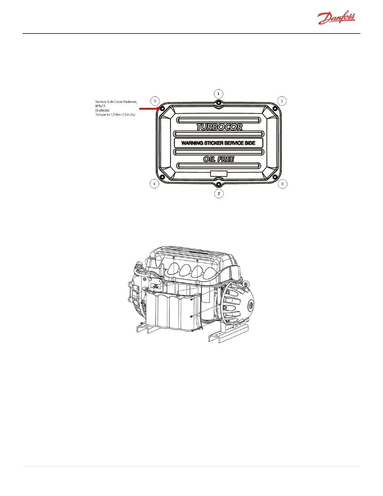
2. PlacetheServiceSideCoverandsecureitwiththeM5x15fastenersaccordingtothesequenceshown
inFigure4-10ServiceSideCoverTorqueSequence.
3. Followthesequencetwice.Thefirsttime,onlytightenthefastenershalfwaydowntoallowfor
adjustment.Torqueto13in.lb.onthesecondpass.
Figure 4-10 Service Side Cover Torque Sequence
4.1.4 Capacitor Cover
TheCapacitorCoverprovidesprotectionforthecapacitors.
Figure 4-11 Capacitor Cover
4.1.4.1 Capacitor Cover Removal and Installation
Capacitor Cover Removal
1. IsolatecompressorpowerasdescribeinSection1.8ElectricalIsolationonpage22.
2. RemovethefastenersthatsecuretheCapacitorCover.
3. Removethecover.
4. Removethenylonnutsunderthecapacitorassembly,thenremovethecapacitorreliefmembrane.
M-SV-001-EN Rev. H-1/23/2023 Page 55 of 294