5. Testeachpintoground;readingshouldbeopenorinfinite.
6. Iftheintegrityofthebearingsensorfeedthroughisinquestion,isolatethecompressor,recoverthe
refrigerantaccordingtoindustrystandards,removethefeedthroughandrepeattheabovesteps
directlyattheinternalsensorconnector.
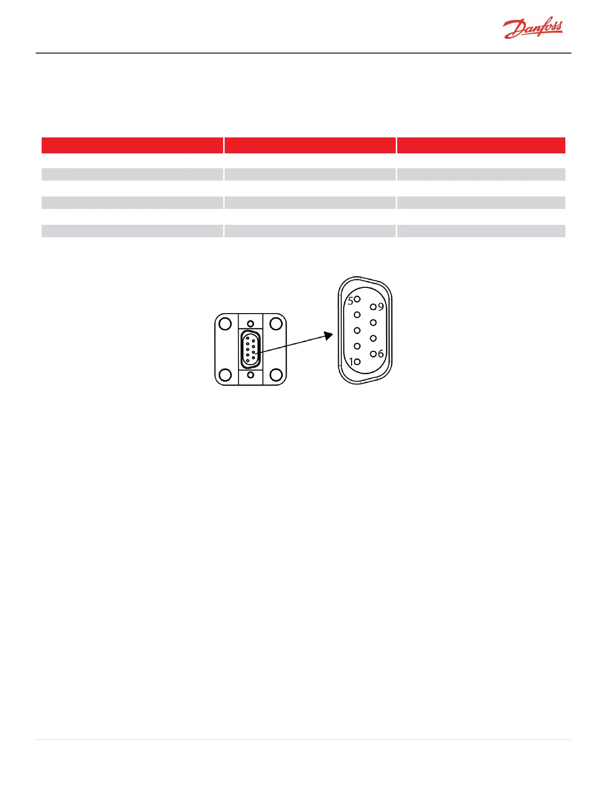
Table 4-48 Bearing Sensor Coil Resistance
Pin Combination Front Sensor Rear Sensor
5-2 2.0Ωto3.5Ω 2.0Ωto3.5Ω
5-3 2.0Ωto3.5Ω 2.0Ωto3.5Ω
6-7 2.0Ωto3.5Ω 2.0Ωto3.5Ω
6-8 2.0Ωto3.5Ω 2.0Ωto3.5Ω
1-4 2.0Ωto3.5Ω Open
1-9 2.0Ωto3.5Ω Open
Figure 4-263 Bearing Sensor Pin Locations
4.30.3.2 Bearing Sensor Cable Verification
Ifanyunexpectedbehaviorexists,itcouldbetheresultofanintermittentconnection.Ifnotproperlydiagnosed,the
issuemayleadtounnecessarilyreplacingcomponentsinthebearingcontrolloop,suchastheBMCC,PWM,Bearing
PowerFeedthroughs,orBearingSensorCables.
Thissectionprovidesverificationdetailsshouldacompressorexperienceabearingfaulttypewhereother
verification,testing,andtroubleshootingprocesseshavenotbeenabletoidentifythecause.
1. RemovetheModbusandInterlockconnectionsfromthecompressorI/OBoard.
2. ConnecttothecompressorusingtheSMTsoftwareandopentheCalibrationTool.
3. Performabearingcalibrationbyclickingon“StartCalibration.”
4. Aftercalibrationiscomplete,reviewthedata.Doallorbitsandgainvaluesappearnormal?
a. Yes:ContinuetoStep5.
b. No:ContinuetoStep7.
5. Performavalidationbyclickingon“Validate.”
6. Aftervalidationiscomplete,didtheshaftlevitateasexpected?
a. Yes:ContinuetoStep21.
b. No:ContinuetoStep7.
7. Isolatecompressorpower.
8. RemovetheServiceSideCover.RefertoSection4.1.3.1ServiceSideCoverRemovalandInstallationon
page54.
9. DisconnecttheBearingSensorCablesfromJ9andJ10attheBackplane.
M-SV-001-EN Rev. H-1/23/2023 Page 237 of 294