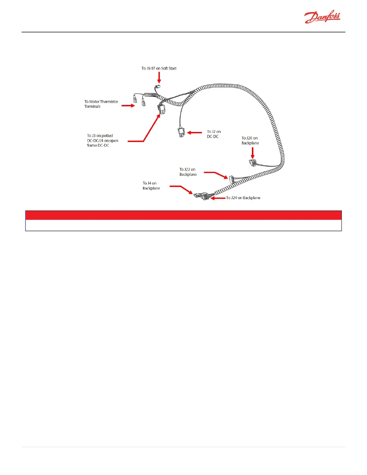
4.24.4 DC-DC Supply Cable Harness
Figure 4-235 DC-DC Harness
NOTE
J4forthePottedDC-DCisnotshown.
4.24.5 DC-DC Harness Removal and Installation
4.24.5.1 DC-DC Harness Removal
1. IsolatethecompressorpowerasdescribedinSection1.8ElectricalIsolationonpage22.
2. RemovetheServiceSideCover.RefertoSection4.1.3.1ServiceSideCoverRemovalandInstallationon
page54.
3. Disconnectthetwo(2)motorthermistorconnectionsfromtheMotorTopPlate.
4. Disconnectthe24and250VDCoutputfromtheDC-DC.RefertoFigure4-229PottedDC-DConpage
206andFigure4-230OpenFrameDC-DConpage206forfurtherdetails.
5. RemovetheSoftStartTemperatureHarnessConnector.Thetwo(2)differentSoftStartvariantshavea
changeintheseconnectors.Bothareapproximatelyinthesamelocation.
a. ForClosed-TopSoftStarts,disconnecttheJ9connector.RefertoFigure4-99Closed-TopSoftStart
J9Connectoronpage118.
b. ForOpen-TopSoftStarts,disconnecttheJ7connector.RefertoFigure4-104Open-TopSoftStartJ7
Connectoronpage120.
6. Carefullycutanycabletiesthatmaybesecuringthecableharnessinplacebothatthetopsideand
serviceside.
7. DisconnectJ4,J20,J22,andJ24fromtheBackplane.RefertoFigure4-238BackplaneConnectionson
page212.
8. CarefullypulltheharnessdownthroughthecablepassageontheServiceSideandremove.Referto
Figure4-236DC-DCHarnessRoutingonpage210.
M-SV-001-EN Rev. H-1/23/2023 Page 209 of 294