Remove power to the frequency converter and remove the
brake resistor.
WARNING/ALARM 28, Brake check failed
The brake resistor is not connected or not working.
Check 2-15 Brake Check.
ALARM 29, Heatsink temp
The maximum temperature of the heatsink has been
exceeded. The temperature fault will not reset until the
temperature falls below the reset heatsink temperature. The
trip and reset points are based on the frequency converter
power size.
Troubleshooting
Check for the following conditions.
Ambient temperature too high.
Motor cable too long.
Incorrect airflow clearance above and below the
frequency converter.
Blocked airflow around the frequency converter.
Damaged heatsink fan.
Dirty heatsink.
ALARM 30, Motor phase U missing
Motor phase U between the frequency converter and the
motor is missing.
Remove power from the frequency converter and check
motor phase U.
ALARM 31, Motor phase V missing
Motor phase V between the frequency converter and the
motor is missing.
Remove power from the frequency converter and check
motor phase V.
ALARM 32, Motor phase W missing
Motor phase W between the frequency converter and the
motor is missing.
Remove power from the frequency converter and check
motor phase W.
ALARM 33, Inrush fault
Too many power-ups have occurred within a short time
period. Let the unit cool to operating temperature.
WARNING/ALARM 34, communication fault
Communication between the and the communication
option card is not operating.
WARNING/ALARM 35, Option fault
An option alarm is received. The alarm is option specific. The
most likely cause is a power-up or a communication fault.
WARNING/ALARM 36, Mains failure
This warning/alarm is only active if the supply voltage to the
frequency converter is lost and 14-10 Mains Failure is NOT set
to [0] No Function. Check the fuses to the frequency
converter and mains power supply to the unit.
ALARM 37, Phase imbalance
There is a current imbalance between the power units
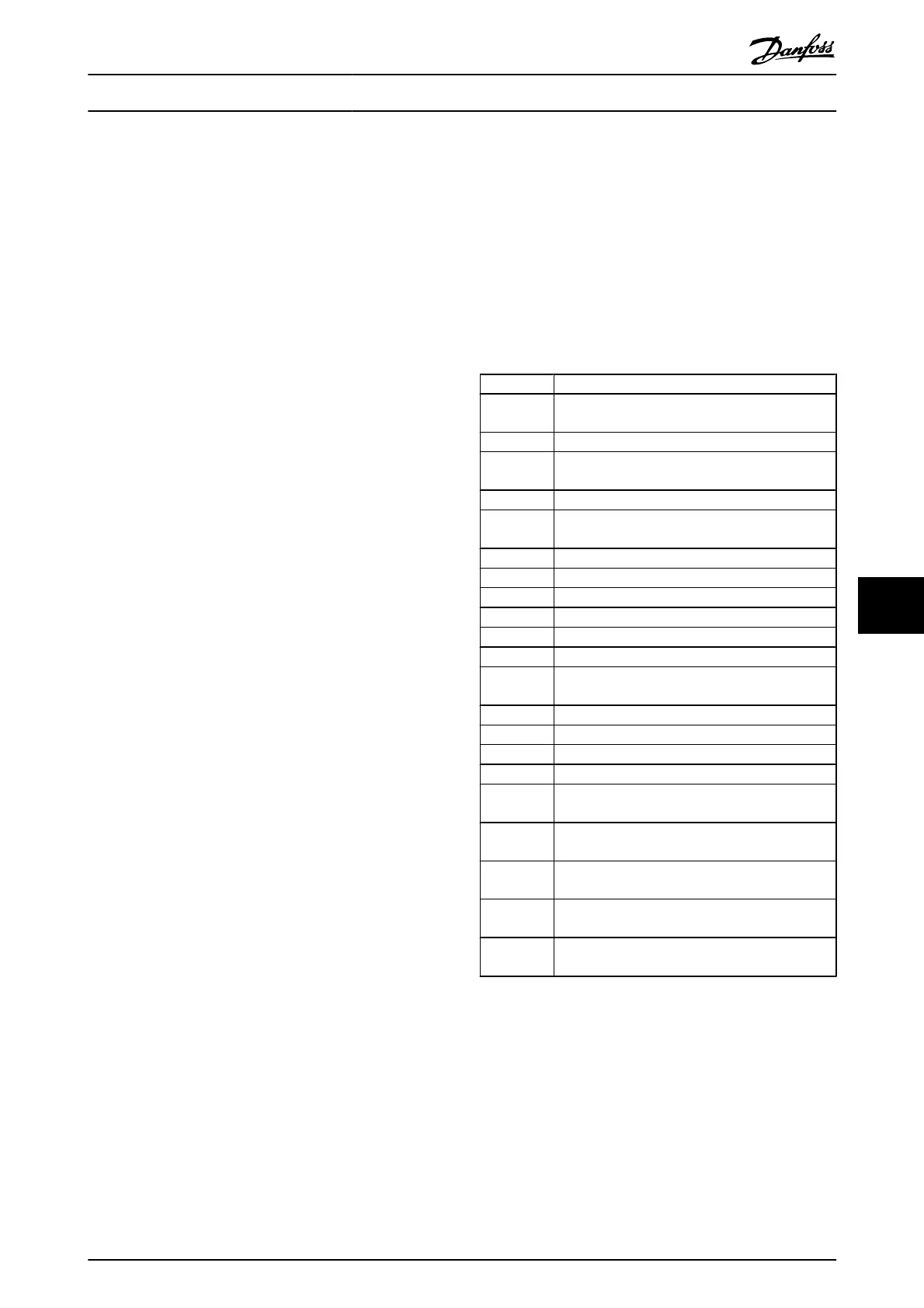
ALARM 38, Internal fault
When an internal fault occurs, a code number defined in the
table below is displayed.
Troubleshooting
Cycle power to the frequency converter.
Check that the option is properly installed.
Check for loose or missing wiring.
It may be necessary to contact your Danfoss supplier or
service department. Note the code number for further
troubleshooting directions.
No. Text
0 Serial port cannot be initialised. Contact
yourDanfoss supplier or DanfossService Department.
256-258 Power EEPROM data is defect or too old
512-519 Internal fault. Contact yourDanfoss supplier or
Danfoss Service Department.
783 Parameter value outside of min/max limits
1024-1284 Internal fault. Contact your Danfoss supplier or the
Danfoss Service Department.
1299 Option SW in slot A is too old
1300 Option SW in slot B is too old
1302 Option SW in slot C1 is too old
1315 Option SW in slot A is not supported (not allowed)
1316 Option SW in slot B is not supported (not allowed)
1318 Option SW in slot C1 is not supported (not allowed)
1379-2819 Internal fault. Contact yourDanfoss supplier or
DanfossService Department.
2820 LCP stack overflow
2821 Serial port overflow
2822 USB port overflow
3072-5122 Parameter value is outside its limits
5123 Option in slot A: Hardware incompatible with
control board hardware
5124 Option in slot B: Hardware incompatible with
control board hardware
5125 Option in slot C0: Hardware incompatible with
control board hardware
5126 Option in slot C1: Hardware incompatible with
control board hardware
5376-6231 Internal fault. Contact yourDanfoss supplier or
DanfossService Department.
ALARM 39, Heatsink sensor
No feedback from the heatsink temperature sensor.
The signal from the IGBT thermal sensor is not available on
the power card. The problem could be on the power card, on
the gate drive card, or the ribbon cable between the power
card and gate drive card.
WARNING 40, Overload of digital output terminal 27
Check the load connected to terminal 27 or remove short-
circuit connection. Check 5-00 Digital I/O Mode and
5-01 Terminal 27 Mode.
Warnings and Alarms
VLT
®
AutomationDrive Operating
Instructions
MG.33.AJ.02 - VLT
®
is a registered Danfoss trademark 55
8

 Loading...


