Safe stop Terminal 37
3, 4)
(Terminal 37 is fixed PNP logic):
Voltage level 0 - 24V DC
Voltage level, logic'0' PNP < 4V DC
Voltage level, logic'1' PNP >20V DC
Maximum voltage on input 28V DC
Nominal input current at 24V 50mA rms
Nominal input current at 20V 60mA rms
Input capacitance 400nF
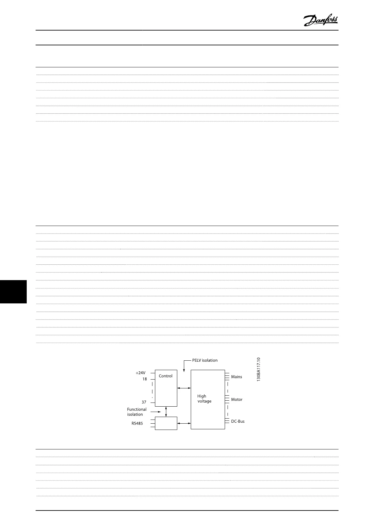
All digital inputs are galvanically isolated from the supply voltage (PELV) and other high-voltage terminals.
1)
Terminals 27 and 29 can also be programmed as output.
2)
Except safe stop input Terminal 37.
3)
Terminal 37 is only available in FC 302 and FC 301 A1 with Safe Stop. It can only be used as safe stop input. Terminal 37 is suitable
for PL d (ISO13849-1), SIL 2 (IEC 61508) and SILCL 2 (EN 62061) and implements a Safe Stop function in accordance with Safe Torque
Off (STO, EN 61800-5-2) and Stop Category 0 (EN 60204-1). Terminal 37 and the Safe Stop function are designed in conformance with
EN 60204-1, EN 61800-5-1, EN 61800-2, EN 61800-3, and EN 954-1. For correct and safe use of the Safe Stop function follow the related
information and instructions in the Design Guide.
4)
When using a contactor with a DC coil inside in combination with Safe Stop, it is important to make a return way for the current
from the coil when turning it off. This can be done by using a freewheel diode (or, alternatively, a 30 or 50 V MOV for quicker response
time) across the coil. Typical contactors can be bought with this diode.
Analog inputs:
Number of analog inputs 2
Terminal number 53, 54
Modes Voltage or current
Mode select Switch S201 and switch S202
Voltage mode Switch S201/switch S202 = OFF (U)
Voltage level FC 301: 0 to + 10/ FC 302: -10 to +10 V (scaleable)
Input resistance, R
i
approx. 10 kΩ
Max. voltage ± 20 V
Current mode Switch S201/switch S202 = ON (I)
Current level 0/4 to 20 mA (scaleable)
Input resistance, R
i
approx. 200 Ω
Max. current 30 mA
Resolution for analog inputs 10 bit (+ sign)
Accuracy of analog inputs Max. error 0.5% of full scale
Bandwidth FC 301: 20 Hz/ FC 302: 100 Hz
The analog inputs are galvanically isolated from the supply voltage (PELV) and other high-voltage terminals.
Pulse/encoder inputs:
Programmable pulse/encoder inputs 2/1
Terminal number pulse/encoder 29
1)
, 33
2)
/ 32
3)
, 33
3)
Max. frequency at terminal 29, 32, 33 110kHz (Push-pull driven)
Max. frequency at terminal 29, 32, 33 5kHz (open collector)
Min. frequency at terminal 29, 32, 33 4Hz
Voltage level see section on Digital input
Specifications
VLT
®
AutomationDrive Operating
Instructions
72 MG.33.AJ.02 - VLT
®
is a registered Danfoss trademark
100
 Loading...


