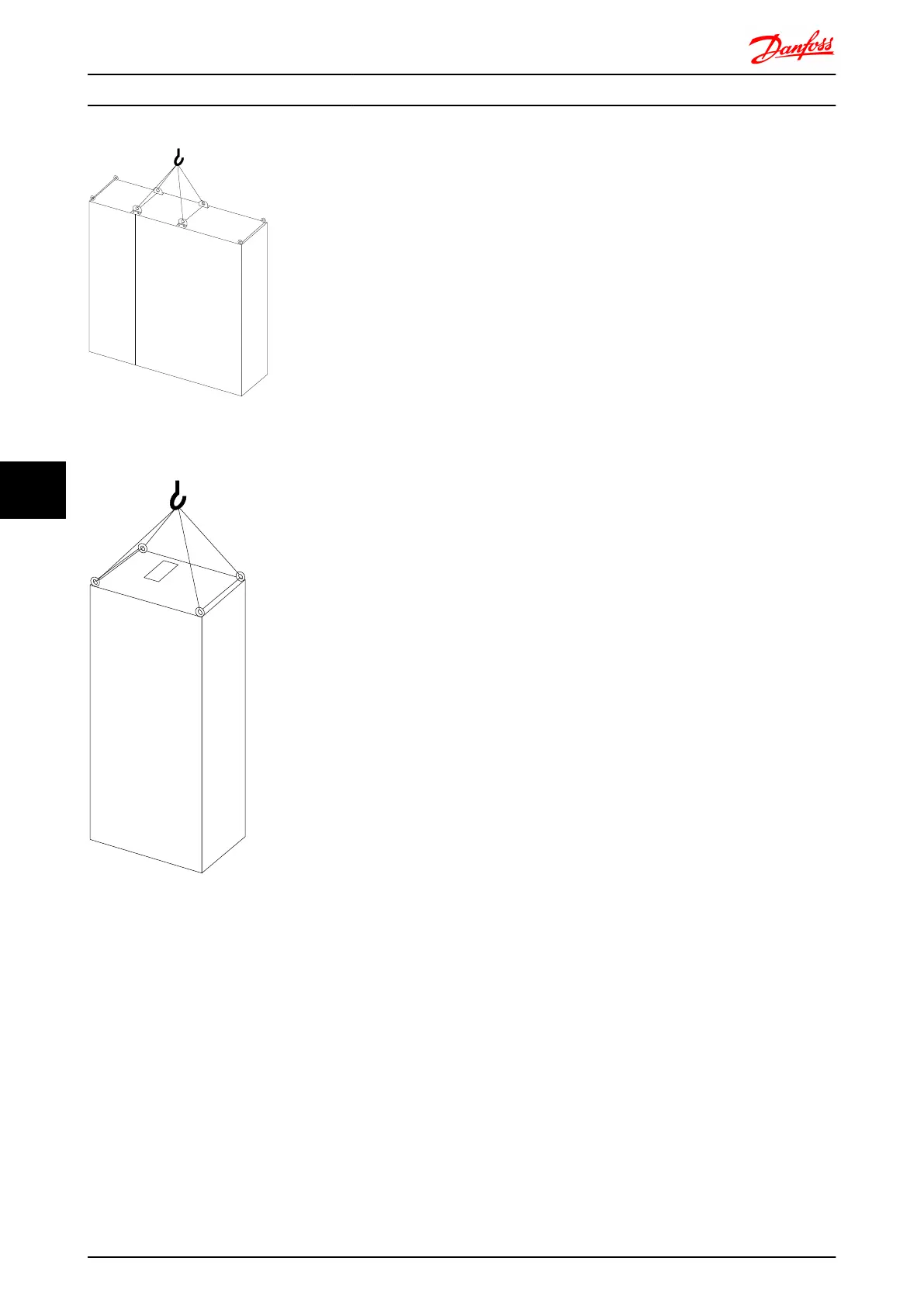
Illustration 7.3 Recommended Lifting Method, Frame Sizes F3,
F4, F11, F12 and F13
Illustration 7.4 Recommended Lifting Method, Frame Sizes F8
NOTE
The plinth is provided in the same packaging as the
frequency converter but is not attached to frame sizes F1-
F4 during shipment. The plinth is required to allow airflow
to the drive to provide proper cooling. The F frames
should be positioned on top of the plinth in the final
installation location. The angle from the top of the drive to
the lifting cable should be 60°C or greater.
In addition to the drawings above a spreader bar is an
acceptable way to lift the F Frame.
Mechanical Installation - ... FC 300 Design Guide
122 MG.33.BD.02 - VLT
®
is a registered Danfoss trademark
77
 Loading...


