1.1.3 Definitions
Frequency converter:
Coast
The motor shaft is in free mode. No torque on motor.
I
MAX
The maximum output current.
I
N
The rated output current supplied by the frequency
converter.
U
MAX
The maximum output voltage.
Input:
Control command
Start and stop the connected motor by means of LCP and
the digital inputs.
Functions are divided into two groups.
Functions in group 1 have higher priority than functions in
group 2.
Group 1 Reset, Coasting stop, Reset and Coasting stop,
Quick-stop, DC braking, Stop and the "Off" key.
Group 2 Start, Pulse start, Reversing, Start reversing, Jog
and Freeze output
Motor:
f
JOG
The motor frequency when the jog function is activated
(via digital terminals).
f
M
Motor frequency. Output from the frequency converter.
Output frequency is related to the shaft speed on motor
depending on number of poles and slip frequency.
f
MAX
The maximum output frequency the frequency converter
applies on its output. The maximum output frequency is
set in limit par. 4-12, 4-13 and 4-19.
f
MIN
The minimum motor frequency from frequency converter.
Default 0 Hz.
f
M,N
The rated motor frequency (nameplate data).
I
M
The motor current.
I
M,N
The rated motor current (nameplate data).
n
M,N
The rated motor speed (nameplate data).
n
s
Synchronous motor speed
n
s
=
2 ×
par
. 1 − 23 × 60
s
par
. 1 − 39
P
M,N
The rated motor power (nameplate data).
T
M,N
The rated torque (motor).
U
M
The instantaneous motor voltage.
U
M,N
The rated motor voltage (nameplate data).
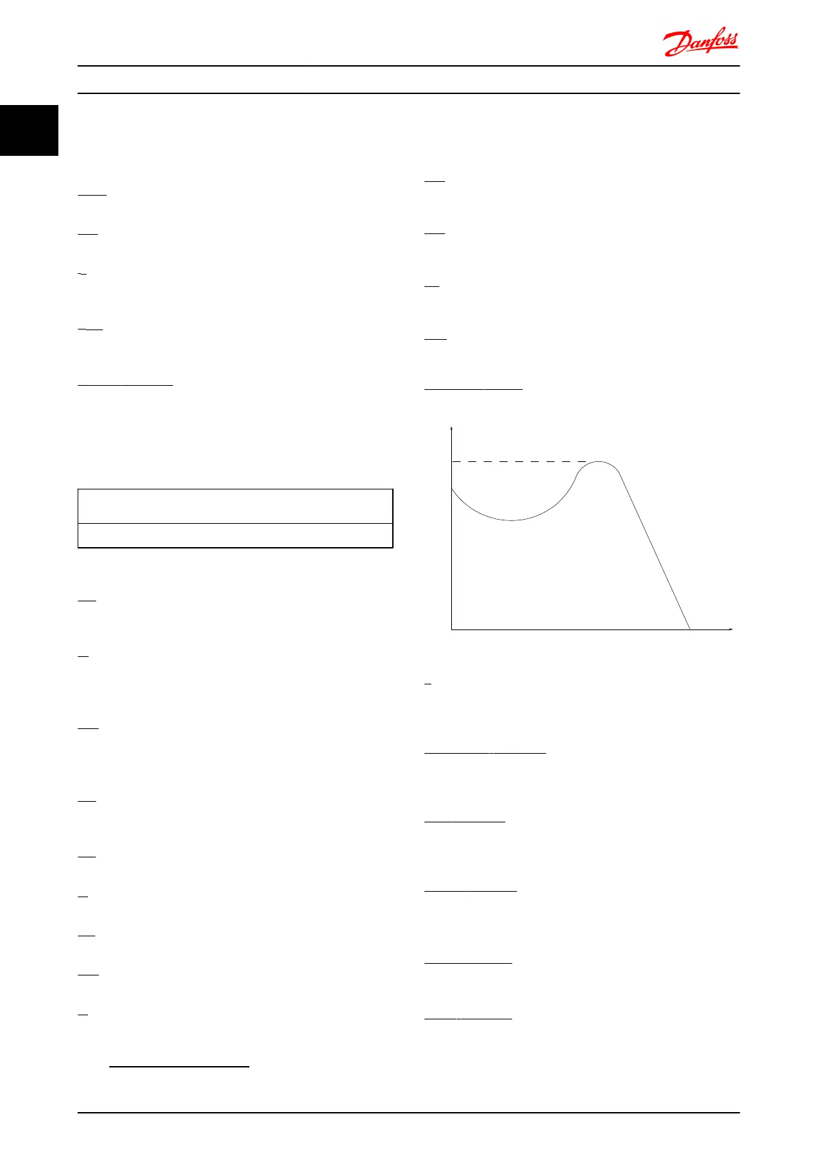
Break-away torque
175ZA078.10
Pull-out
rpm
Torque
η
The efficiency of the frequency converter is defined as the
ratio between the power output and the power input.
Start-disable command
A stop command belonging to the group 1 control
commands - see this group.
Stop command
See Control commands.
References:
Analog Reference
An analog signal applied to input 53 or 54. The signal can
be either Voltage 0-10V (FC 301 and FC 302) or -10 -+10V
(FC 302). Current signal 0-20 mA or 4-20 mA.
Binary Reference
A signal applied to the serial communication port (RS-485
term 68 – 69).
Preset Reference
A defined preset reference to be set from -100% to +100%
of the reference range. Selection of eight preset references
via the digital terminals.
How to Read this Design Gui... FC 300 Design Guide
8 MG.33.BD.02 - VLT
®
is a registered Danfoss trademark
11
 Loading...


