8.10.1 Mains Supply Interference/
Harmonics
A frequency converter takes up a non-sinusoidal current
from mains, which increases the input current I
RMS
. A non-
sinusoidal current is transformed by means of a Fourier
analysis and split up into sine-wave currents with different
frequencies, i.e. different harmonic currents I
N
with 50 Hz
as the basic frequency:
Harmonic currents I
1
I
5
I
7
Hz 50 Hz 250 Hz 350 Hz
The harmonics do not affect the power consumption
directly but increase the heat losses in the installation
(transformer, cables). Consequently, in plants with a high
percentage of rectifier load, maintain harmonic currents at
a low level to avoid overload of the transformer and high
temperature in the cables.
NOTE
Some of the harmonic currents might disturb communi-
cation equipment connected to the same transformer or
cause resonance in connection with power-factor
correction batteries.
Harmonic currents compared to the RMS input current:
Input current
I
RMS
1.0
I
1
0.9
I
5
0.4
I
7
0.2
I
11-49
< 0.1
To ensure low harmonic currents, the frequency converter
is equipped with intermediate circuit coils as standard. DC-
coils reduce the total harmonic distortion (THD) to 40%.
8.10.2
The Effect of Harmonics in a Power
Distribution System
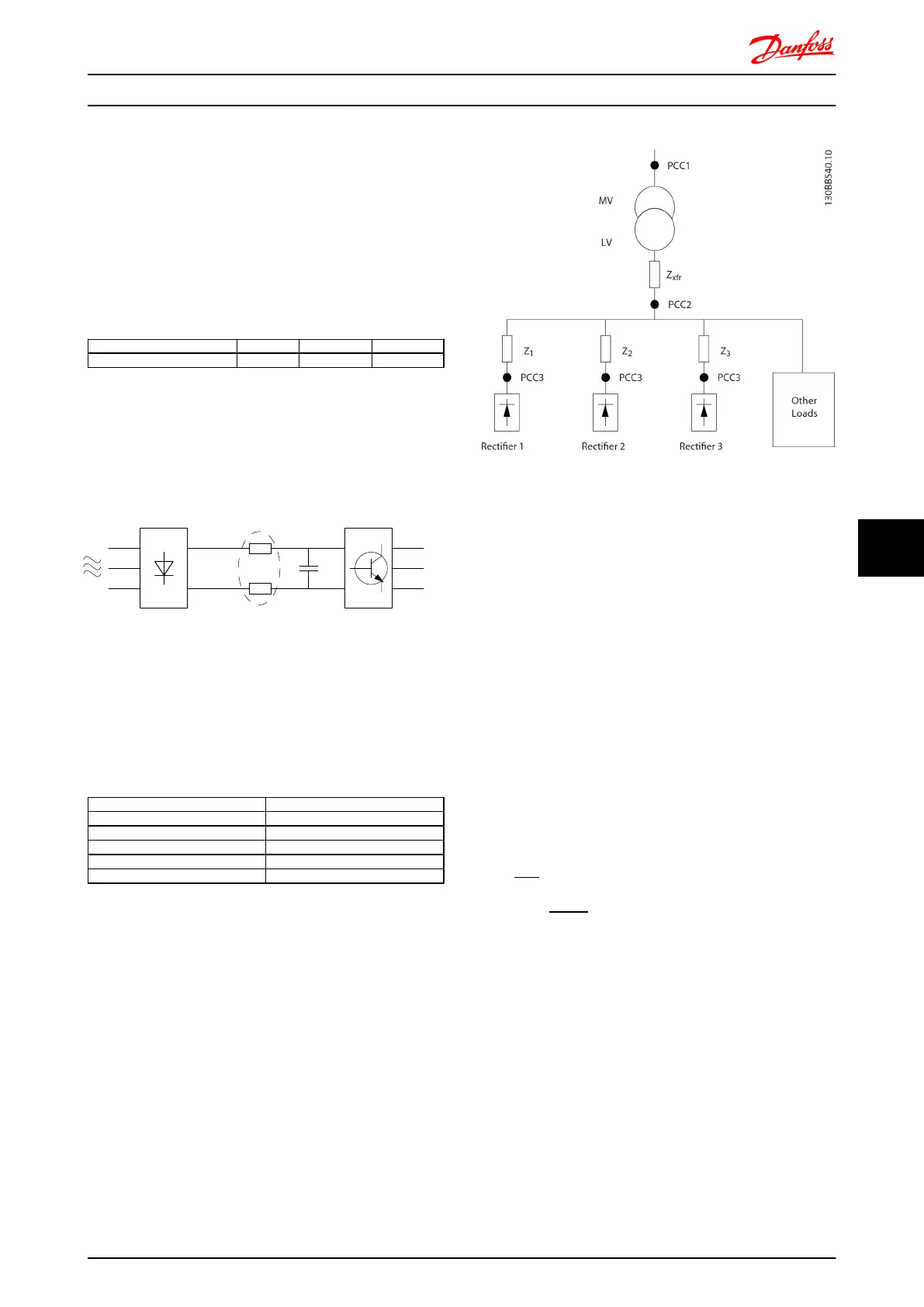
In Illustration 8.65 a transformer is connected on the
primary side to a point of common coupling PCC1, on the
medium voltage supply. The transformer has an
impedance Z
xfr
and feeds a number of loads. The point of
common coupling where all loads are connected together
is PCC2. Each load is connected through cables that have
an impedance Z
1
, Z
2
, Z
3
.
Illustration 8.65 Small Distribution System
Harmonic currents drawn by non-linear loads cause
distortion of the voltage because of the voltage drop on
the impedances of the distribution system. Higher
impedances result in higher levels of voltage distortion.
Current distortion relates to apparatus performance and it
relates to the individual load. Voltage distortion relates to
system performance. It is not possible to determine the
voltage distortion in the PCC knowing only the load’s
harmonic performance. In order to predict the distortion in
the PCC the configuration of the distribution system and
relevant impedances must be known.
A commonly used term for describing the impedance of a
grid is the short circuit ratio R
sce
, defined as the ratio
between the short circuit apparent power of the supply at
the PCC (S
sc
) and the rated apparent power of the load
(S
equ
).
R
sce
=
S
ce
S
equ
where
S
sc
=
U
2
Z
supply
and
S
equ
=
U
×
I
equ
The negative effect of harmonics is twofold
•
Harmonic currents contribute to system losses (in
cabling, transformer)
•
Harmonic voltage distortion causes disturbance
to other loads and increase losses in other loads
Electrical Installation FC 300 Design Guide
MG.33.BD.02 - VLT
®
is a registered Danfoss trademark 225
8 8

 Loading...


