Mechanical dimensions, 12-Pulse units, frame sizes F8-F13
Frame size F8 F9 F10 F11 F12 F13
High overload rated
power - 160% overload
torque
250 - 400kW
(380 - 500V)
355 - 560kW
(525-690V)
250 - 400kW
(380 - 500V)
355 - 56kW
(525-690V)
450 - 630kW
(380 - 500V)
630 - 800kW
(525-690V)
450 - 630kW
(380 - 500V)
630 - 800kW
(525-690V)
710 - 800kW
(380 - 500V)
900 - 1200kW
(525-690V)
710 - 800kW
(380 - 500V)
900 - 1200kW
(525-690V)
IP
NEMA
21, 54
Type 1/Type 12
21, 54
Type 1/Type 12
21, 54
Type 1/Type 12
21, 54
Type 1/Type 12
21, 54
Type 1/Type 12
21, 54
Type 1/Type 12
Shipping
dimensions
[mm]
Height 2324 2324 2324 2324 2324 2324
Width 970 1568 1760 2559 2160 2960
Depth 1130 1130 1130 1130 1130 1130
Drive
dimensions
[mm]
Height 2204 2204 2204 2204 2204 2204
Width 800 1400 1600 2200 2000 2600
Depth 606 606 606 606 606 606
Max weight [kg] 440 656 880 1096 1022 1238
7.2 Mechanical Installation
Preparation of the mechanical installation of the frequency
converter must be done carefully to ensure a proper result
and to avoid additional work during installation. Start
taking a close look at the mechanical drawings at the end
of this instruction to become familiar with the space
demands.
7.2.1 Tools Needed
To perform the mechanical installation the following tools
are needed:
•
Drill with 10 or 12 mm drill
•
Tape measure
•
Wrench with relevant metric sockets (7-17 mm)
•
Extensions to wrench
•
Sheet metal punch for conduits or cable glands
in IP 21/Nema 1 and IP 54 units
•
Lifting bar to lift the unit (rod or tube max. Ø 25
mm (1 inch), able to lift minimum 400 kg (880
lbs)).
•
Crane or other lifting aid to place the frequency
converter in position
•
A Torx T50 tool is needed to install the E1 in IP21
and IP54 enclosure types.
7.2.2
General Considerations
Wire access
Ensure that proper cable access is present including
necessary bending allowance. As the IP00 enclosure is
open to the bottom cables must be fixed to the back
panel of the enclosure where the frequency converter is
mounted, i.e. by using cable clamps.
CAUTION
All cable lugs/ shoes must mount within the width of the
terminal bus bar.
Space
Ensure proper space above and below the frequency
converter to allow airflow and cable access. In addition
space in front of the unit must be considered to enable
opening of the door of the panel.
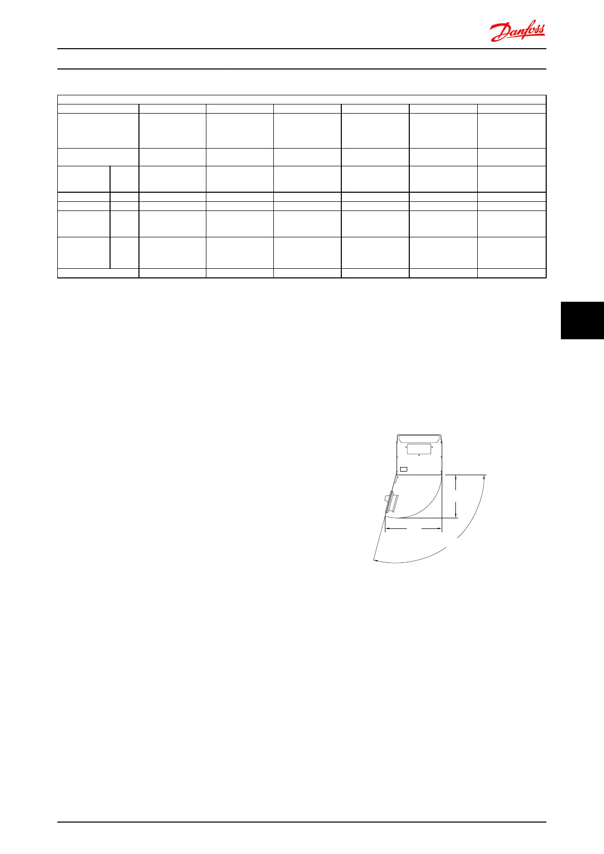
176FA235.11
<105,0°
526
(20.7)
399
(15.7)
Illustration 7.5 Space in front of IP21/IP54 enclosure type, frame
size D1 and D2 .
Mechanical Installation - ... FC 300 Design Guide
MG.33.BD.02 - VLT
®
is a registered Danfoss trademark 133
7 7
 Loading...


