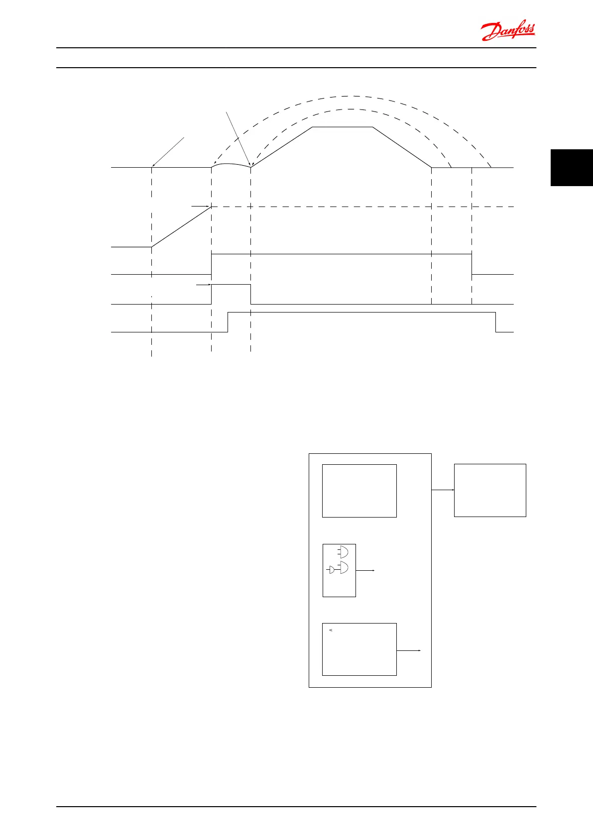
Mech.
Brake
Gain
Boost
Relay
Torque
ref.
Motor
Speed
Premag Torque Ramp
Time
p. 2-27
Torque Ref. 2-26
Gain Boost Factor
p. 2-28
Brake
Release
Time
p. 2-25
Ramp 1 up
p. 3-41
Ramp 1 down
p. 3-42
Stop
Delay
p. 2-24
Activate
Brake
Delay
p. 2-23
1 2 3
130BA642.12
II
I
Illustration 3.14 Brake release sequence for hoist mechanical brake control
I) Activate brake delay: The frequency converter starts again from the mechanical brake engaged position.
II) Stop delay: When the time between successive starts is shorter than the setting in 2-24 Stop Delay, the frequency converter starts
without applying the mechanical brake (e.g. reversing).
NOTE
For an example of advanced mechanical brake control for
hoisting applications, see section Application Examples
3.9.3 Brake Resistor Cabling
EMC (twisted cables/shielding)
To reduce the electrical noise from the wires between the
brake resistor and the frequency converter, the wires must
be twisted.
For enhanced EMC performance a metal screen can be
used.
3.10 Smart Logic Controller
Smart Logic Control (SLC) is essentially a sequence of user
defined actions (see 13-52 SL Controller Action [x]) executed
by the SLC when the associated user defined event (see
13-51 SL Controller Event [x]) is evaluated as TRUE by the
SLC.
The condition for an event can be a particular status or
that the output from a Logic Rule or a Comparator
Operand becomes TRUE. That will lead to an associated
Action as illustrated:
. . .
. . .
Par. 13-43
Comparator Operator
Par. 13-43
Logic Rule Operator 2
Par. 13-51
SL Controller Event
Par. 13-51
SL Controller Action
130BB671.10
Coast
Start timer
Set Do X low
Select set-up 2
. . .
Running
Warning
Torque limit
Digital inpute X 30/2
. . .
=
TRUE longer than..
. . .
. . .
Events and actions are each numbered and linked together
in pairs (states). This means that when event [0] is fulfilled
(attains the value TRUE), action [0] is executed. After this,
the conditions of event [1] will be evaluated and if
evaluated TRUE, action [1] will be executed and so on.
Only one event will be evaluated at any time. If an event is
Introduction to FC 300 FC 300 Design Guide
MG.33.BD.02 - VLT
®
is a registered Danfoss trademark 47
3
3

 Loading...


