evaluated as FALSE, nothing happens (in the SLC) during
the current scan interval and no other events will be
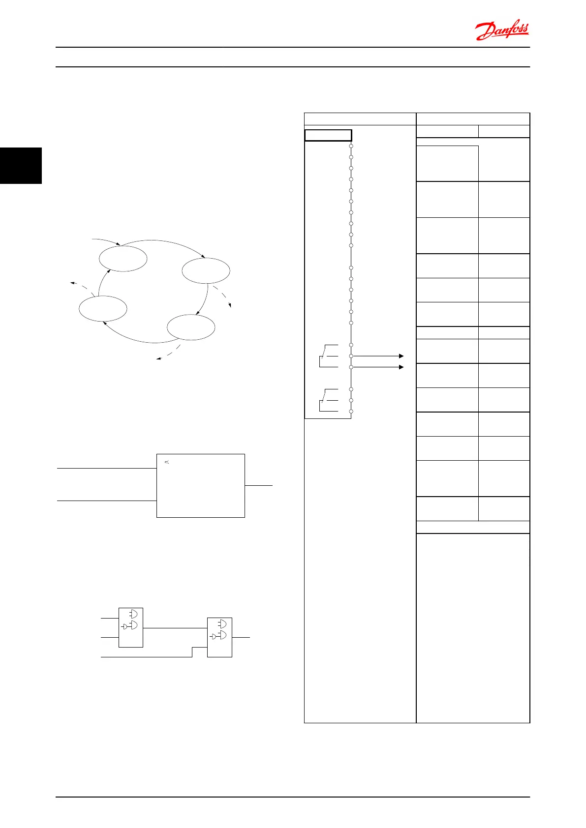
evaluated. This means that when the SLC starts, it
evaluates event [0] (and only event [0]) each scan interval.
Only when event [0] is evaluated TRUE, will the SLC
execute action [0] and start evaluating event [1]. It is
possible to programme from 1 to 20 events and actions.
When the last event / action has been executed, the
sequence starts over again from event [0] / action [0]. The
illustration shows an example with three event / actions:
130BA062.13
State 1
Event 1/
Action 1
State 2
Event 2/
Action 2
Start
event P13-01
State 3
Event 3/
Action 3
State 4
Event 4/
Action 4
Stop
event P13-02
Stop
event P13-02
Stop
event P13-02
Comparators
Comparators are used for comparing continuous variables
(i.e. output frequency, output current, analog input etc.) to
fixed preset values.
Par. LC-11
Comparator Operator
=
TRUE longer than.
. . .
. . .
Par. LC-10
Comparator Operand
Par. LC-12
Comparator Value
130BB672.10
Logic Rules
Combine up to three boolean inputs (TRUE / FALSE inputs)
from timers, comparators, digital inputs, status bits and
events using the logical operators AND, OR, and NOT.
. . .
. . .
. . .
. . .
Par. LC-43
Logic Rule Operator 2
Par. LC-41
Logic Rule Operator 1
Par. LC-40
Logic Rule Boolean 1
Par. LC-42
Logic Rule Boolean 2
Par. LC-44
Logic Rule Boolean 3
130BB673.10
Application Example
Parameters
FC
+24 V
+24 V
D IN
D IN
D IN
COM
D IN
D IN
D IN
D IN
+10 V
A IN
A IN
COM
A OUT
COM
R1R2
12
13
18
19
20
27
29
32
33
37
50
53
54
55
42
39
01
02
03
04
05
06
130BB839.10
Function Setting
4-30 Motor
Feedback Loss
Function
[1] Warning
4-31 Motor
Feedback Speed
Error
100RPM
4-32 Motor
Feedback Loss
Timeout
5 sec
7-00 Speed PID
Feedback Source
[2] MCB 102
17-11 Resolution
(PPR)
1024*
13-00 SL
Controller Mode
[1] On
13-01 Start Event
[19] Warning
13-02 Stop Event
[44] Reset
key
13-10 Comparato
r Operand
[21] Warning
no.
13-11 Comparato
r Operator
[1] ≈*
13-12 Comparato
r Value
90
13-51 SL
Controller Event
[22]
Comparator 0
13-52 SL
Controller Action
[32] Set
digital out A
low
5-40 Function
Relay
[80] SL digital
output A
* = Default Value
Notes/comments:
If the limit in the feedback
monitor is exceeded, Warning
90 will be issued. The SLC
monitors Warning 90 and in the
case that Warning 90 becomes
TRUE then Relay 1 is triggered.
External equipment may then
indicate that service may be
required. If the feedback error
goes below the limit again
within 5 sec. then the drive
continues and the warning
disappears. But Relay 1 will still
be triggered until [Reset] on
the LCP.
Table 3.9 Using SLC to Set a Relay
Introduction to FC 300 FC 300 Design Guide
48 MG.33.BD.02 - VLT
®
is a registered Danfoss trademark
3
3

 Loading...


