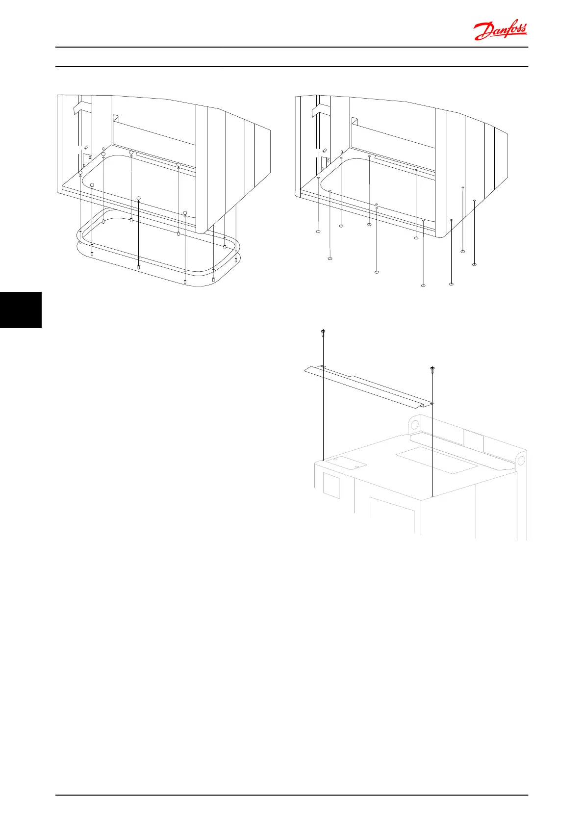
Illustration 7.51 Mounting of bottom plate,frame size E1.
The bottom plate of the E1 can be mounted from either
in- or outside of the enclosure, allowing flexibility in the
installation process, i.e. if mounted from the bottom the
glands and cables can be mounted before the frequency
converter is placed on the pedestal.
7.2.11 IP21 Drip Shield Installation (Frame
size D1 and D2 )
To comply with the IP21 rating, a separate drip shield is
to be installed as explained below:
•
Remove the two front screws
•
Insert the drip shield and replace screws
•
Torque the screws to 5,6 Nm (50 in-lbs)
Illustration 7.52 Drip shield installation.
Mechanical Installation - ... FC 300 Design Guide
156 MG.33.BD.02 - VLT
®
is a registered Danfoss trademark
77

 Loading...


