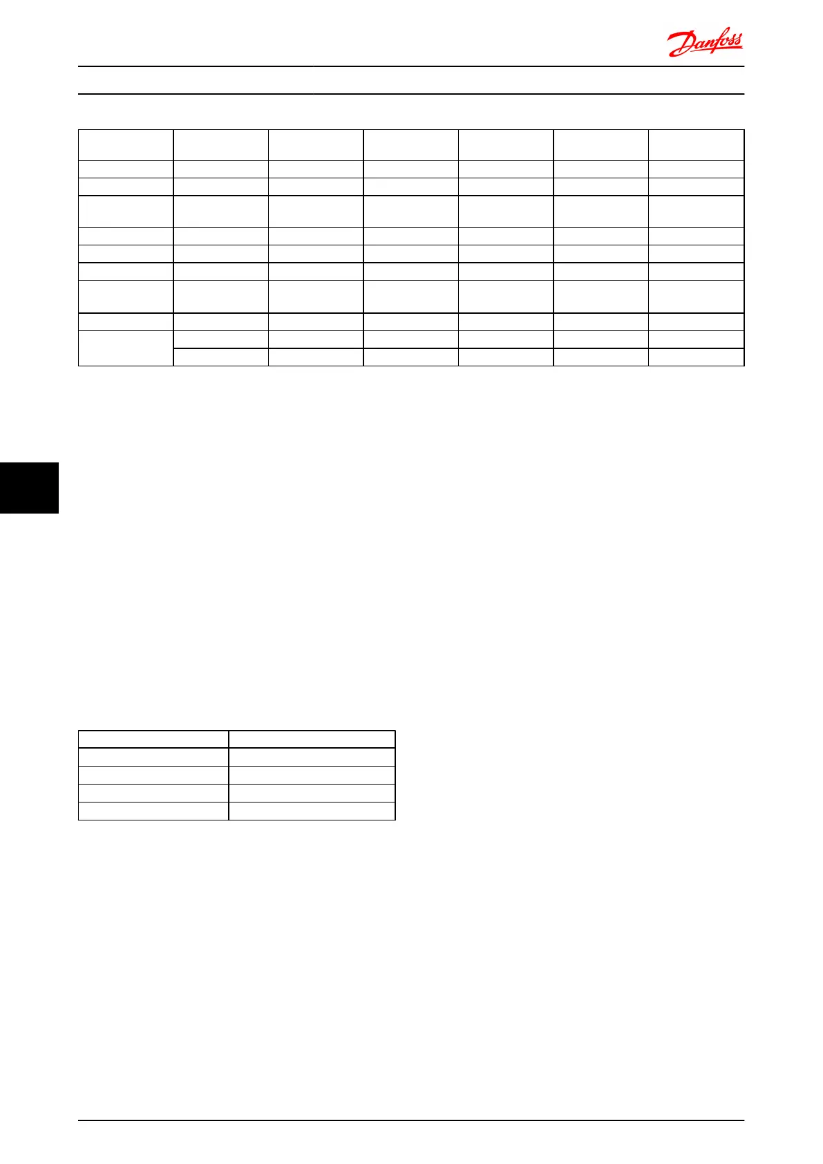
Frame Size Power Size [kW] Voltage [V] 1 cable [m] 2 cables [m] 3 cables [m] 4 cables [m]
A1, A2, A5 0.37-0.75 400 150 45 8 6
500 150 7 4 3
A2, A5 1.1-1.5 400 150 45 20 8
500 150 45 5 4
A2, A5 2.2-4 400 150 45 20 11
500 150 45 20 6
A3, A5 5.5-7.5 400 150 45 20 11
500 150 45 20 11
B1, B2, B3, B4,
C1, C2, C3, C4
11-75 400 150 75 50 37
500 150 75 50 37
Problems may arise at start and at low RPM values if motor sizes are widely different because small motors' relatively high
ohmic resistance in the stator calls for a higher voltage at start and at low RPM values.
The electronic thermal relay (ETR) of the frequency
converter cannot be used as motor protection for the
individual motor of systems with parallel-connected
motors. Provide further motor protection by e.g.
thermistors in each motor or individual thermal relays.
(Circuit breakers are not suitable as protection).
8.5.4 Motor Insulation
For motor cable lengths ≤ the maximum cable length
listed in the General Specifications tables the following
motor insulation ratings are recommended because the
peak voltage can be up to twice the DC link voltage, 2.8
times the mains voltage, due to transmission line effects in
the motor cable. If a motor has lower insulation rating it
recommended to use a du/dt or sine wave filter.
Nominal Mains Voltage Motor Insulation
U
N
≤ 420 V
Standard U
LL
= 1300V
420V < U
N
≤ 500 V Reinforced U
LL
= 1600V
500V < U
N
≤ 600 V Reinforced U
LL
= 1800V
600V < U
N
≤ 690 V Reinforced U
LL
= 2000V
8.5.5 Motor Bearing Currents
All motors installed with FC 302 90 kW or higher power
drives should have NDE (Non-Drive End) insulated bearings
installed to eliminate circulating bearing currents. To
minimize DE (Drive End) bearing and shaft currents proper
grounding of the drive, motor, driven machine, and motor
to the driven machine is required.
Standard Mitigation Strategies:
1. Use an insulated bearing
2. Apply rigorous installation procedures
- Ensure the motor and load motor are
aligned
- Strictly follow the EMC Installation
guideline
- Reinforce the PE so the high frequency
impedance is lower in the PE than the
input power leads
- Provide a good high frequency
connection between the motor and the
frequency converter for instance by
screened cable which has a 360°
connection in the motor and the
frequency converter
- Make sure that the impedance from
frequency converter to building ground
is lower that the grounding impedance
of the machine. This can be difficult for
pumps
- Make a direct earth connection between
the motor and load motor
3. Lower the IGBT switching frequency
4. Modify the inverter waveform, 60° AVM vs.
SFAVM
5. Install a shaft grounding system or use an
isolating coupling
6. Apply conductive lubrication
7. Use minimum speed settings if possible
8. Try to ensure the line voltage is balanced to
ground. This can be difficult for IT, TT, TN-CS or
Grounded leg systems
9. Use a dU/dt or sinus filter
Electrical Installation FC 300 Design Guide
208 MG.33.BD.02 - VLT
®
is a registered Danfoss trademark
88
 Loading...


