9.1.1 Encoder Connection
The purpose of this guideline is to ease the set-up of
encoder connection to the frequency converter. Before
setting up the encoder the basic settings for a closed loop
speed control system will be shown.
See also 10.2 Encoder Option MCB 102
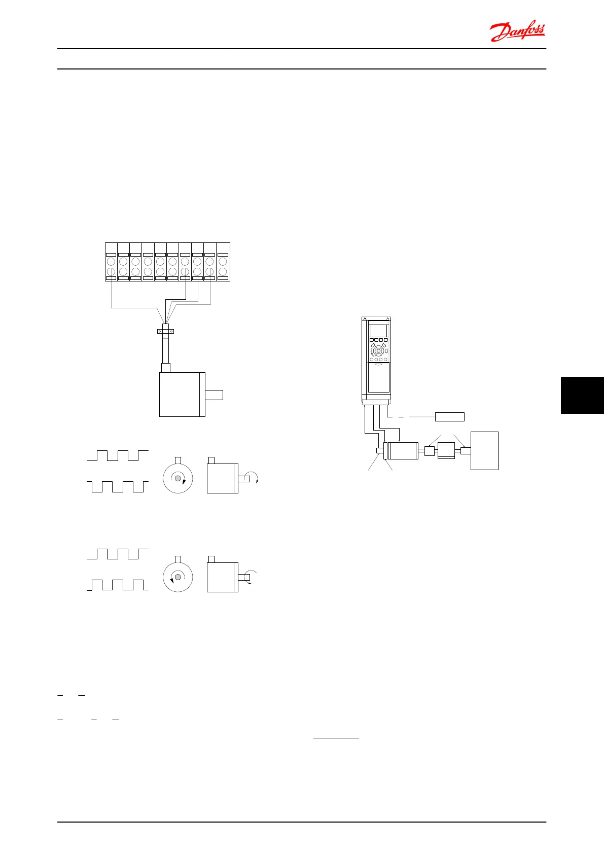
Encoder Connection to the frequency converter
130BA090.11
+24V DC
A
B
GND
1312 18 37322719 29 33 20
24V or 10-30V encoder
Illustration 9.1 24V incremental encoder. Max. cable length 5 m.
9.1.2
Encoder Direction
The direction of encoder is determined by which order the
pulses are entering the drive.
Clockwise direction means channel A is 90 electrical
degrees before channel B.
Counter Clockwise direction means channel B is 90
electrical degrees before A.
The direction determined by looking into the shaft end.
9.1.3
Closed Loop Drive System
A drive system consist usually of more elements such as:
•
Motor
•
Add
(Gearbox)
(Mechanical Brake)
•
FC 302
•
Encoder as feed-back system
•
Brake resistor for dynamic braking
•
Transmission
•
Load
Applications demanding mechanical brake control will
usually need a brake resistor.
Motor
Gearbox
Load
Transmission
Encoder Mech. brake
Brake resistor
130BA120.10
Illustration 9.2 Basic Set-up for FC 302 Closed Loop Speed
Control
9.1.4
Programming of Torque Limit and
Stop
In applications with an external electro-mechanical brake,
such as hoisting applications, it is possible to stop the
frequency converter via a 'standard' stop command and
simultaneously activate the external electro-mechanical
brake.
The example given below illustrates the programming of
frequency converter connections.
The external brake can be connected to relay 1 or 2, see
paragraph Control of Mechanical Brake. Program terminal
27 to Coast, inverse [2] or Coast and Reset, inverse [3], and
program terminal 29 to Terminal mode 29 Output [1] and
Torque limit & stop [27].
Description:
If a stop command is active via terminal 18 and the
frequency converter is not at the torque limit, the motor
ramps down to 0 Hz.
Application Examples FC 300 Design Guide
MG.33.BD.02 - VLT
®
is a registered Danfoss trademark 233
9 9

 Loading...


