1 How to Read this Design Guide
This Design Guide will introduce all aspects of your FC 300.
Available literature for FC 300
- The VLT AutomationDrive Operating Instructions
MG.33.AX.YY provide the neccessary information
for getting the drive up and running.
- The VLT AutomationDrive High Power Operating
Instructions MG.33.UX.YY
- The VLT AutomationDrive Design Guide MG.
33.BX.YY entails all technical information about
the drive and customer design and applications.
- The VLT AutomationDrive Programming Guide
MG.33.MX.YY provides information on how to
programme and includes complete parameter
descriptions.
- The VLT AutomationDrive Profibus Operating
Instructions MG.33.CX.YY provide the information
required for controlling, monitoring and
programming the drive via a Profibus fieldbus.
- The VLT AutomationDrive DeviceNet Operating
Instructions MG.33.DX.YY provide the information
required for controlling, monitoring and
programming the drive via a DeviceNet fieldbus.
X = Revision number
YY = Language code
Danfoss Drives technical literature is also available online
at www.danfoss.com/BusinessAreas/DrivesSolutions/
Documentations/Technical+Documentation.
1.1.1
Symbols
Symbols used in this guide.
NOTE
Indicates something to be noted by the reader.
CAUTION
Indicates a potentially hazardous situation which, if not
avoided, may result in minor or moderate injury or
equipment damage.
WARNING
Indicates a potentially hazardous situation which, if not
avoided, could result in death or serious injury.
*
Indicates default setting
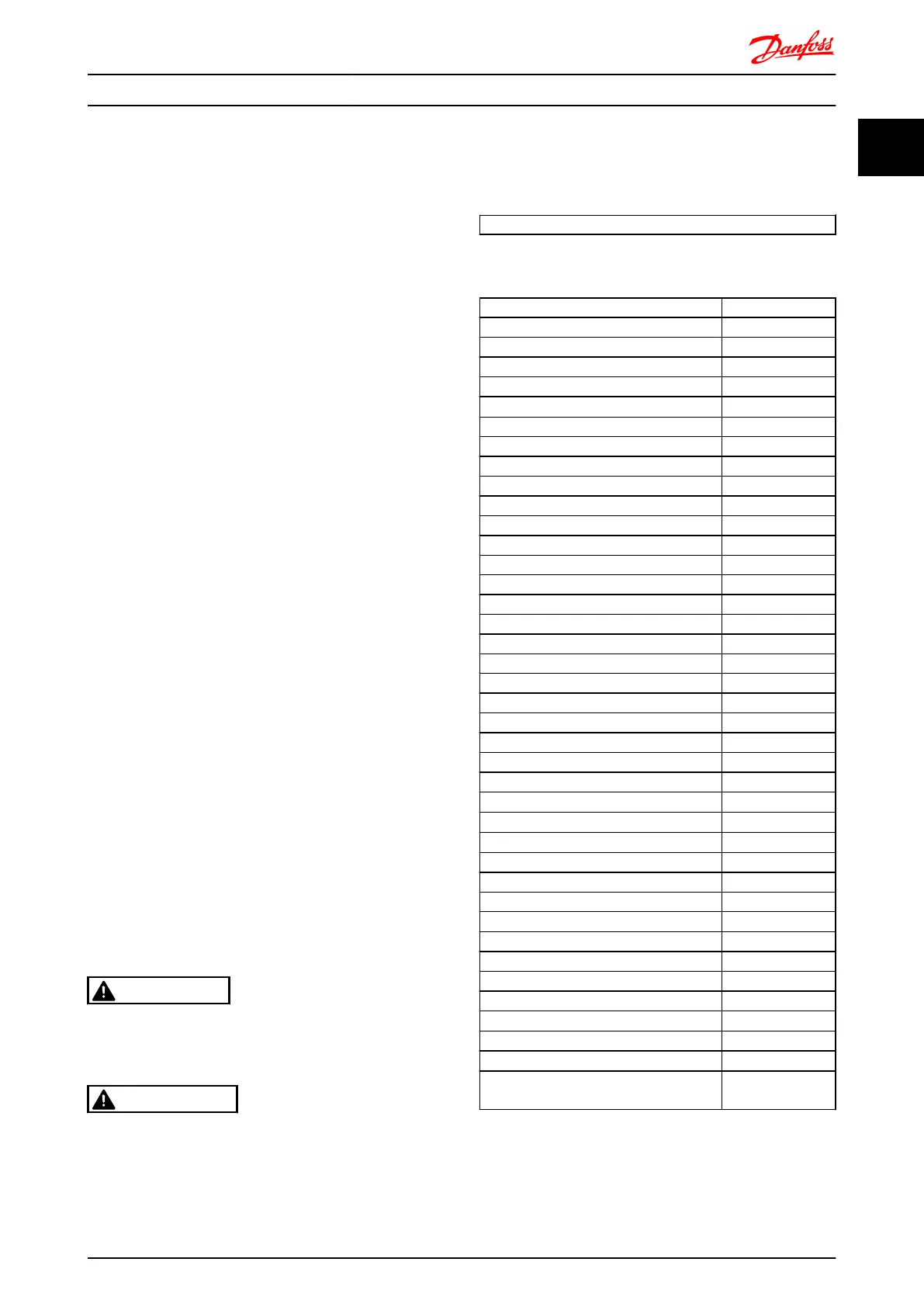
1.1.2 Abbreviations
Alternating current AC
American wire gauge AWG
Ampere/AMP A
Automatic Motor Adaptation AMA
Current limit I
LIM
Degrees Celsius
°C
Direct current DC
Drive Dependent D-TYPE
Electro Magnetic Compatibility EMC
Electronic Thermal Relay ETR
frequency converter FC
Gram g
Hertz Hz
Horsepower hp
Kilohertz kHz
Local Control Panel LCP
Meter m
Millihenry Inductance mH
Milliampere mA
Millisecond ms
Minute min
Motion Control Tool MCT
Nanofarad nF
Newton Meters Nm
Nominal motor current I
M,N
Nominal motor frequency f
M,N
Nominal motor power P
M,N
Nominal motor voltage U
M,N
Parameter par.
Protective Extra Low Voltage PELV
Printed Circuit Board PCB
Rated Inverter Output Current I
INV
Revolutions Per Minute RPM
Regenerative terminals Regen
Second sec.
Synchronous Motor Speed n
s
Torque limit T
LIM
Volts V
The maximum output current I
VLT,MAX
The rated output current supplied by the
frequency converter
I
VLT,N
How to Read this Design Gui... FC 300 Design Guide
MG.33.BD.02 - VLT
®
is a registered Danfoss trademark 7
1 1
 Loading...


