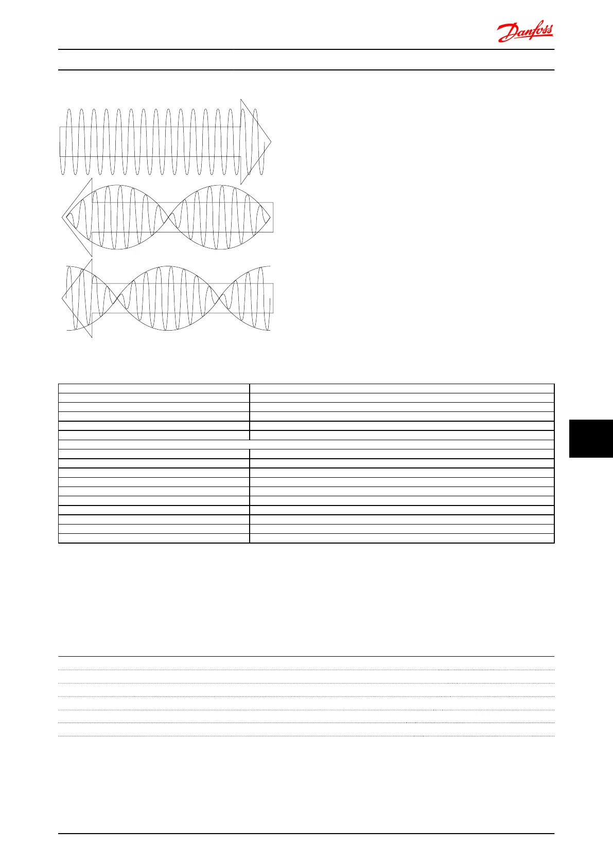
Set-up example
In this example a Permanent Magnet (PM) Motor is used
with resolver as speed feedback. A PM motor must usually
operate in flux mode.
Wiring:
The max cable length is 150m when a twisted pair type of
cable is used.
NOTE
Resolver cables must be screened and separated from the
motor cables.
NOTE
The screen of the resolver cable must be correctly
connected to the de-coupling plate and connected to
chassis (earth) on the motor side.
NOTE
Always use screened motor cables and brake chopper
cables.
1-00 Configuration Mode
Speed closed loop [1]
1-01 Motor Control Principle
Flux with feedback [3]
1-10 Motor Construction
PM, non salient SPM [1]
1-24 Motor Current
Nameplate
1-25 Motor Nominal Speed
Nameplate
1-26 Motor Cont. Rated Torque
Nameplate
AMA is not possible on PM motors
1-30 Stator Resistance (Rs)
Motor data sheet
30-80 d-axis Inductance (Ld)
Motor data sheet (mH)
1-39 Motor Poles
Motor data sheet
1-40 Back EMF at 1000 RPM
Motor data sheet
1-41 Motor Angle Offset
Motor data sheet (Usually zero)
17-50 Poles
Resolver data sheet
17-51 Input Voltage
Resolver data sheet
17-52 Input Frequency
Resolver data sheet
17-53 Transformation Ratio
Resolver data sheet
17-59 Resolver Interface
Enabled [1]
Table 10.1 Adjust following parameters
10.5 Relay Option MCB 105
The MCB 105 option includes 3 pieces of SPDT contacts and must be fitted into option slot B.
Electrical Data:
Max terminal load (AC-1)
1)
(Resistive load) 240V AC 2A
Max terminal load (AC-15 )
1)
(Inductive load @ cosφ 0.4) 240 V AC 0.2A
Max terminal load (DC-1)
1)
(Resistive load) 24V DC 1 A
Max terminal load (DC-13)
1)
(Inductive load) 24V DC 0.1 A
Min terminal load (DC) 5V 10mA
Max switching rate at rated load/min load 6 min
-1
/20 sec
-1
1) IEC 947 part 4 and 5
Options and Accessories FC 300 Design Guide
MG.33.BD.02 - VLT
®
is a registered Danfoss trademark 241
10
10
 Loading...


