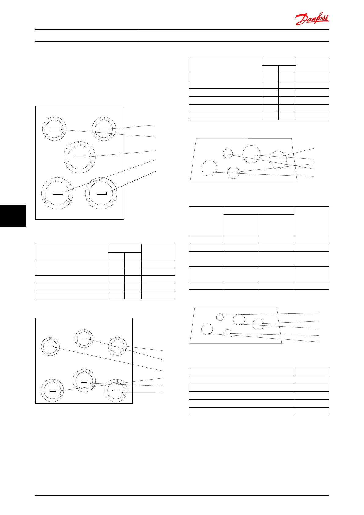
Cable entry holes
The suggested use of the holes are purely recommen-
dations and other solutions are possible. Unused cable
entry holes can be sealed with rubber grommets (for IP
21).
* Tolerance ± 0.2 mm
[4]
[5]
[1]
[3]
[2]
130BB656.10
Illustration 8.14 A2 - IP21
Hole Number and recommended
use
Dimensions
1)
Nearest metric
UL [in] [mm]
1) Mains 3/4 28.4 M25
2) Motor 3/4 28.4 M25
3) Brake/Load S 3/4 28.4 M25
4) Control Cable 1/2 22.5 M20
5) Control Cable 1/2 22.5 M20
1)
Tolerance
±
0.2 mm
[4]
[5]
[6]
[1]
[3]
[2]
130BB657.10
Illustration 8.15 A3 - IP21
Hole Number and recommended
use
Dimensions
1)
Nearest metric
UL [in] [mm]
1) Mains 3/4 28.4 M25
2) Motor 3/4 28.4 M25
3) Brake/Load Sharing 3/4 28.4 M25
4) Control Cable 1/2 22.5 M20
5) Control Cable 1/2 22.5 M20
6) Control Cable 1/2 22.5 M20
1)
Tolerance
±
0.2 mm
[5]
[3]
[2]
[4]
[1]
130BB663.10
Illustration 8.16 A4 - IP55
Hole Number
and
recommended
use
Dimensions
1)
Nearest metric
UL [in] [mm]
1) Mains 3/4 28.4 M25
2) Motor 3/4 28.4 M25
3) Brake/Load
Sharing
3/4 28.4 M25
4) Control
Cable
1/2 22.5 M20
5) Removed - - -
1)
Tolerance
±
0.2 mm
[4]
[2]
[3]
[5]
[1]
130BB665.10
Illustration 8.17 A4 - IP55 threaded gland holes
Hole Number and recommended use Dimensions
1) Mains M25
2) Motor M25
3) Brake/Load Sharing M25
4) Control Cable M16
5) Control Cable M20
Electrical Installation FC 300 Design Guide
164 MG.33.BD.02 - VLT
®
is a registered Danfoss trademark
88

 Loading...


