NOTICE!
POTENTIAL EQUALIZATION!
Electrical interference risks disturbing the entire installation, when the ground potential between the adjustable
frequency drive and the system is different. To avoid electrical interference, install equalizing cables between the
system components. Recommended cable cross-section: 16 mm
2
.
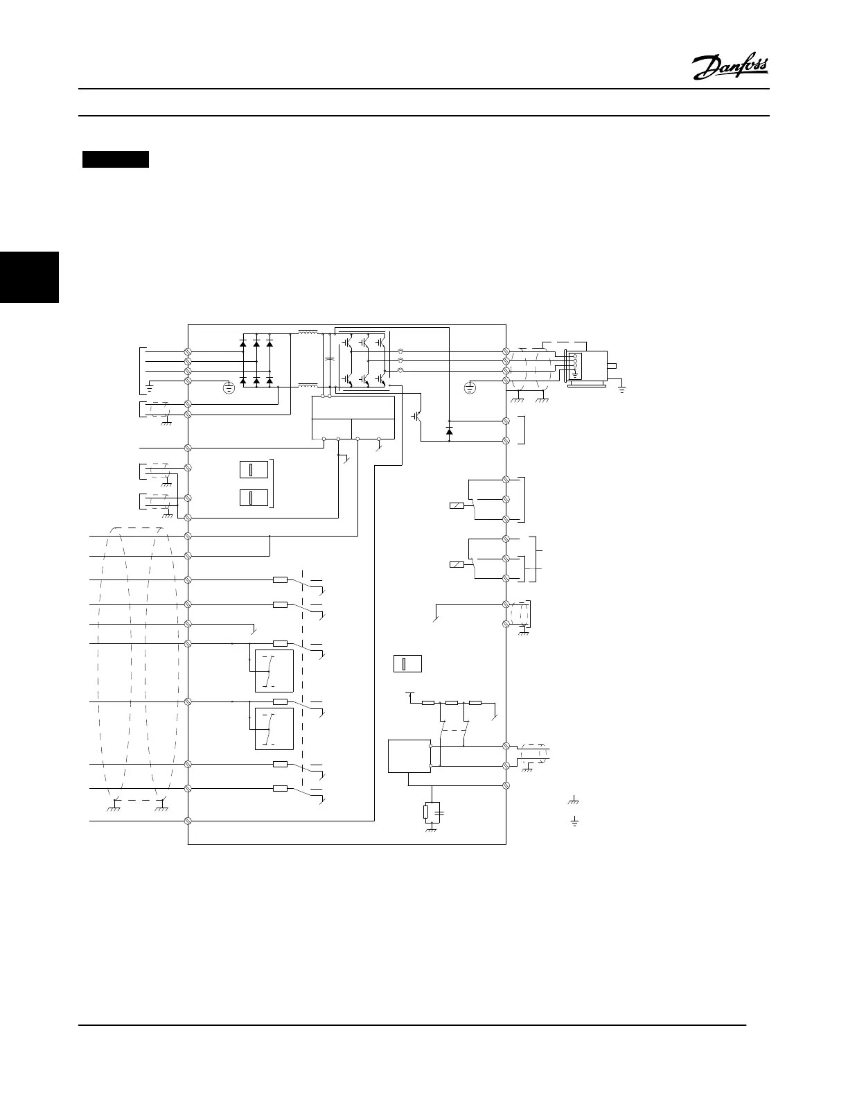
4.4 Wiring Schematic
130BD552.11
3-phase
power
input
DC bus
Switch Mode
Power Supply
Motor
Analog Output
Interface
relay1
relay2
ON=Terminated
OFF=Open
Brake
resistor
91 (L1)
92 (L2)
93 (L3)
PE
88 (-)
89 (+)
50 (+10 V OUT)
53 (A IN)
54 (A IN)
55 (COM A IN)
0/4-20 mA
12 (+24 V OUT)
13 (+24 V OUT)
37 (D IN)
18 (D IN)
20 (COM D IN)
10 V DC
15 mA 130/200 mA
+ - + -
(U) 96
(V) 97
(W) 98
(PE) 99
(COM A OUT) 39
(A OUT) 42
(P RS-485) 68
(N RS-485) 69
(COM RS-485) 61
0 V
5V
S801
0/4-20 mA
RS-485
RS-485
03
+10 V DC
0/-10 V DC -
+10 V DC
+10 V DC
0/4-20 mA
0/-10 V DC-
240 V AC, 2 A
24 V DC
02
01
05
04
06
24 V (NPN)
0 V (PNP)
0 V (PNP)
24 V (NPN)
19 (D IN)
24 V (NPN)
0 V (PNP)
27
24 V
0 V
(D IN/OUT)
0 V (PNP)
24 V (NPN)
(D IN/OUT)
0 V
24 V
29
24 V (NPN)
0 V (PNP)
0 V (PNP)
24 V (NPN)
33 (D IN)
32 (D IN)
1 2
ON
A53
ON
21
A54
ON=0/4-20 mA
OFF=0/-10 V DC -
+10 V DC
95
P 5-00
21
ON
S801
(R+) 82
(R-) 81
: Chassis
: Ground
**
240 V AC, 2 A
400 V AC, 2 A
*
Figure 4.1 Basic Wiring Schematic
A=Analog, D=Digital
*Terminal 37 (optional) is used for Safe Torque Off. For Safe Torque Off installation instructions, refer to the Safe Torque Off
Instruction Manual for Danfoss VLT
®
Adjustable Frequency Drives.
**Do not connect cable shield.
Electrical Installation
VLT
®
HVAC Drive Instruction Manual
14 MG11AJ22 - Rev. 2013-09-13
44
 Loading...


