4.8 Control Wiring
•
Isolate control wiring from high power components
in the adjustable frequency drive.
•
When the adjustable frequency drive is connected
to a thermistor, ensure that the thermistor control
wiring is shielded and reinforced/double insulated.
A 24 V DC supply voltage is recommended.
4.8.1 Control Terminal Types
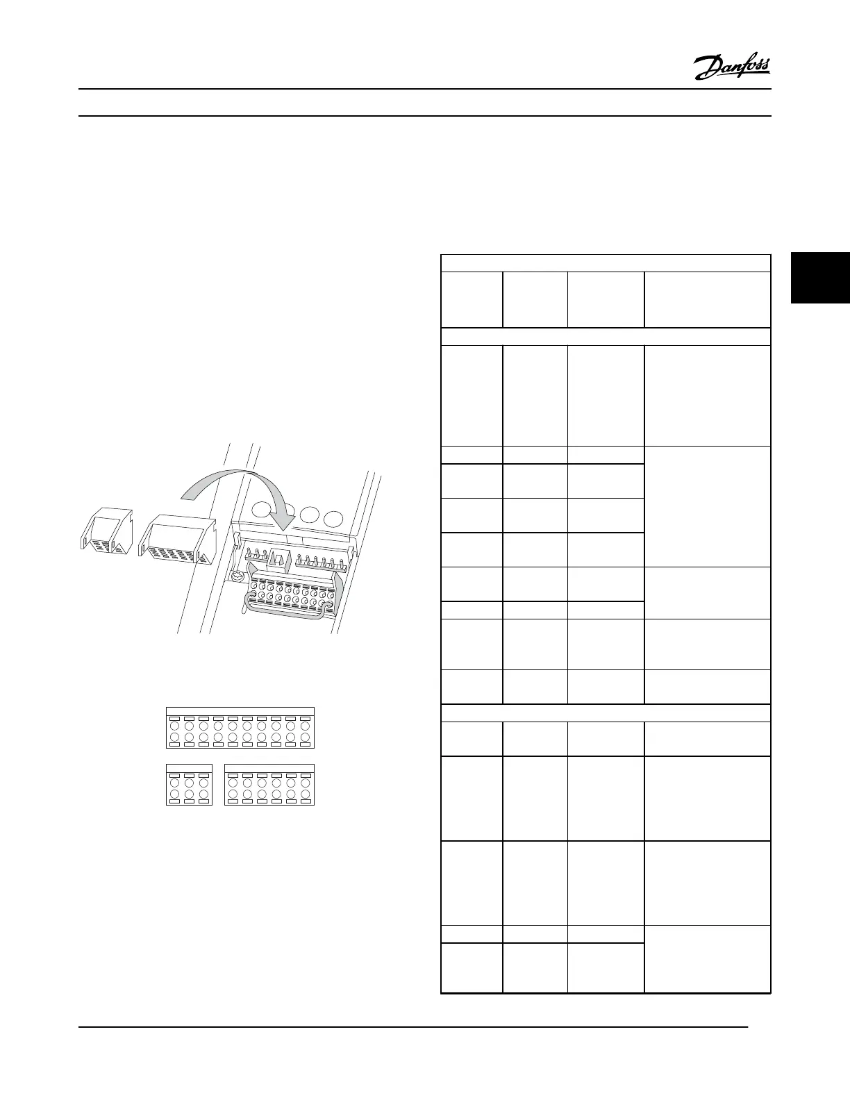
Figure 4.11 shows the removable adjustable frequency drive
connectors. Terminal functions and default settings are
summarized in Table 4.3.
Figure 4.11 Control Terminal Locations
12 13 18 19 27 29 32 33 20 37
39 42 50 53 54 55
61 68 69
130BB931.10
1
2 3
Figure 4.12 Terminal Numbers
•
Connector 1 provides four programmable digital
inputs terminals, two additional digital terminals
programmable as either input or output, a 24 V DC
terminal supply voltage, and a common for optional
customer supplied 24 V DC voltage.
•
Connector 2 terminals (+)68 and (-)69 are for an
RS-485 serial communications connection
•
Connector 3 provides two analog inputs, one
analog output, 10 V DC supply voltage, and
commons for the inputs and output
•
Connector 4 is a USB port available for use with the
MCT 10 Set-up Software
Terminal description
Terminal Parameter
Default
Setting Description
Digital Inputs/Outputs
12, 13 - +24 V DC 24 V DC supply voltage.
Maximum output
current is 200 mA total
for all 24 V loads. Usable
for digital inputs and
external transducers.
18 5-10 [8] Start
Digital inputs.
19 5-11 [0] No
operation
32 5-14 [0] No
operation
33 5-15 [0] No
operation
27 5-12 [2] Coast
inverse
Selectable for digital
input and output.
Default setting is input.
29 5-13 [14] JOG
20 - Common for digital
inputs and 0 V potential
for 24 V supply.
37 - Safe Torque
Off (STO)
Safe input (optional).
Used for STO.
Analog Inputs/Outputs
39 -
Common for analog
output.
42 6-50 Speed 0 -
High Limit
Programmable analog
output. The analog
signal is 0–20 mA or 4–
20 mA at a maximum of
500 Ω.
50 - +10 V DC 10 V DC analog supply
voltage. 15 mA
maximum commonly
used for potentiometer
or thermistor.
53 6-1 Reference Analog input. Selectable
for voltage or current.
Switches A53 and A54
select mA or V.
54 6-2 Feedback
Electrical Installation
VLT
®
HVAC Drive Instruction Manual
MG11AJ22 - Rev. 2013-09-13 19
4 4
 Loading...


