NOTICE!
EMC INTERFERENCE!
Use separated shielded cables for input power, motor
wiring and control wiring, or run cables in three separate
metallic conduits. Failure to isolate power, motor and
control wiring can result in unintended behavior or
reduced performance. Minimum 200 mm (7.9 in) clearance
between control cables, motor and line power.
4.5 Access
•
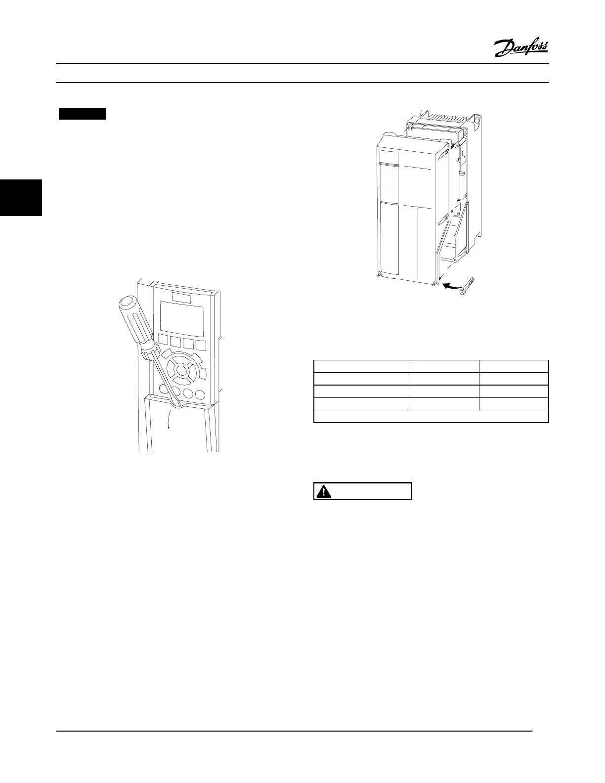
Remove cover with a screwdriver (See Figure 4.3) or
by loosening attaching screws (See Figure 4.4).
Figure 4.3 Access to Wiring for IP20 and IP21 Enclosures
Figure 4.4 Access to Wiring for IP55 and IP66 Enclosures
See Table 4.2 before tightening the covers.
Enclosure IP55 IP66
A4/A5 2 2
B1/B2 2.2 2.2
C1/C2 2.2 2.2
No screws to tighten for A2/A3/B3/B4/C3/C4.
Table 4.2 Tightening Torques for Covers [Nm]
4.6
Motor Connection
WARNING
INDUCED VOLTAGE!
Induced voltage from output motor cables that run
together can charge equipment capacitors even with the
equipment turned off and locked out. Failure to run output
motor cables separately or use shielded cables or metal
conduits could result in death or serious injury.
•
Comply with local and national electrical codes for
cable sizes. For maximum wire sizes, see
8.1 Electrical Data.
•
Follow the motor manufacturer wiring
requirements.
•
Motor wiring knockouts or access panels are
provided at the base of IP21 (NEMA1/12) and
higher units.
Electrical Installation
VLT
®
HVAC Drive Instruction Manual
16 MG11AJ22 - Rev. 2013-09-13
44
 Loading...


