5.3 Local Control Panel Operation
5.3.1 Local Control Panel
The local control panel (LCP) is the combined display and
keypad on the front of the unit.
The LCP has several user functions:
•
Start, stop, and control speed when in local control
•
Display operational data, status, warnings and
cautions
•
Programming adjustable frequency drive functions
•
Manually reset the adjustable frequency drive after
a fault when auto-reset is inactive
An optional numeric LCP (NLCP) is also available. The NLCP
operates in a manner similar to the LCP. See the
Programming Guide for details on use of the NLCP.
NOTICE!
For commissioning via PC, install MCT 10 Set-up Software.
The software is available for downloading at
www.danfoss.com/BusinessAreas/DrivesSolutions/software-
download (basic version) or for ordering (advanced version,
order number 130B1000).
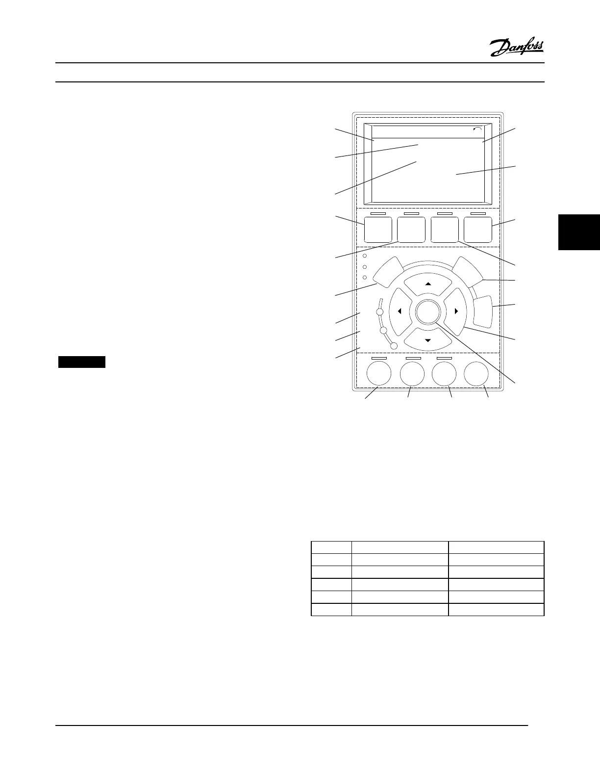
5.3.2 LCP Layout
The LCP is divided into four functional groups (see
Figure 5.1).
A. Display area
B. Display menu keys
C. Navigation keys and indicator lights (LEDs)
D. Operation keys and reset
130BD512.10
Auto
on
Reset
Hand
on
O
Status
Quick
Menu
Main
Menu
Alarm
Log
Back
Cancel
Info
OK
Status
1(1)
0.00 kW
O Remote Stop
0.0Hz
On
Alarm
Warn.
A
0.00 A
0.0 %
B
C
D
2605 kWh
1
2
3
4
5
6
7
8
9
10
11
12
13
14
15
16
17
18 19 20 21
Figure 5.1 Local Control Panel (LCP)
A. Display Area
The display area is activated when the adjustable frequency
drive receives power from AC line voltage, a DC bus terminal,
or an external 24 V DC supply.
The information displayed on the LCP can be customized for
user application. Select options in the Quick Menu Q3-13
Display Settings.
Display Parameter number Default setting
1 0-20 Reference %
2 0-21 Motor current
3 0-22 Power [kW]
4 0-23 Frequency
5 0-24 kWh counter
Table 5.1 Legend to Figure 5.1, Display Area
B. Display Menu Keys
Menu keys are used for menu access for parameter set-up,
toggling through status display modes during normal
operation, and viewing fault log data.
Commissioning
VLT
®
HVAC Drive Instruction Manual
MG11AJ22 - Rev. 2013-09-13 25
5 5
 Loading...


