4.8.3 Enabling Motor Operation (Terminal 27)
A jumper wire may be required between terminal 12 (or 13)
and terminal 27 for the adjustable frequency drive to operate
when using factory default programming values.
•
Digital input terminal 27 is designed to receive an
24 V DC external interlock command. In many
applications, the user wires an external interlock
device to terminal 27
•
When no interlock device is used, wire a jumper
between control terminal 12 (recommended) or 13
to terminal 27. This provides an internal 24 V signal
on terminal 27.
•
No signal present prevents the unit from operating.
•
When the status line at the bottom of the LCP
reads AUTO REMOTE COAST, this indicates that the
unit is ready to operate but is missing an input
signal on terminal 27.
•
When factory installed optional equipment is wired
to terminal 27, do not remove that wiring
NOTICE!
The adjustable frequency drive cannot operate without a
signal on terminal 27 unless terminal 27 is re-programmed.
4.8.4 Voltage/Current Input Selection
(Switches)
The analog input terminals 53 and 54 allow setting of input
signal to voltage (0–10 V) or current (0/4–20 mA).
Default parameter settings:
•
Terminal 53: speed reference signal in open-loop
(see 16-61 Terminal 53 Switch Setting).
•
Terminal 54: feedback signal in closed-loop (see
16-63 Terminal 54 Switch Setting).
NOTICE!
Remove power to the adjustable frequency
drive before changing switch positions.
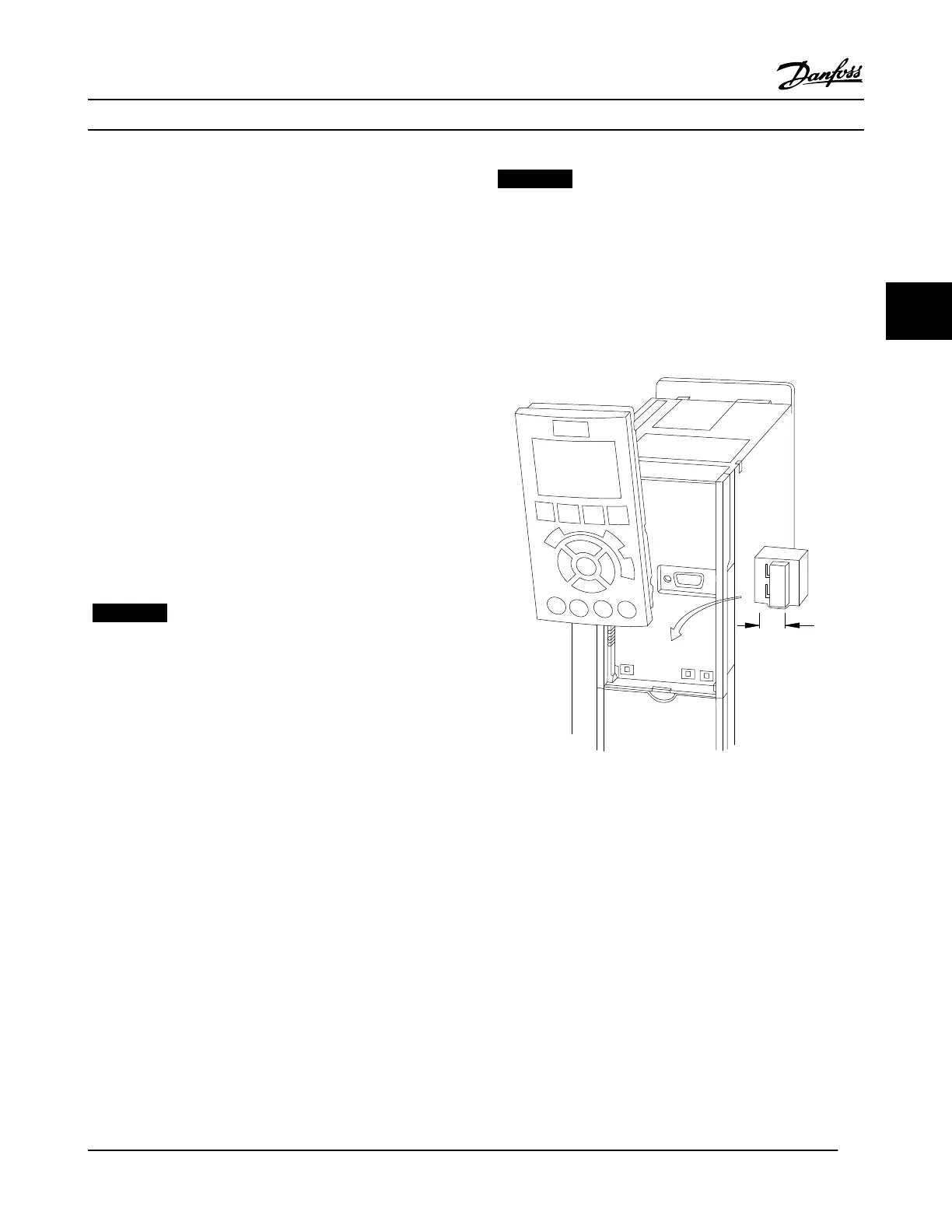
1.
Remove the local control panel (see Figure 4.14).
2. Remove any optional equipment covering the
switches.
3. Set switches A53 and A54 to select the signal type.
U selects voltage, I selects current.
130BD530.10
1
2
N O
VLT
BUSTER.
OFF-ON
A53 A54
U- I U- I
Figure 4.14 Location of Terminals 53 and 54 Switches
4.8.5
Safe Torque Off (STO)
To run Safe Torque Off, additional wiring for the adjustable
frequency drive is required, refer to Safe Torque Off
Instruction Manual for Danfoss VLT
®
Adjustable Frequency
Drives for further information.
Electrical Installation
VLT
®
HVAC Drive Instruction Manual
MG11AJ22 - Rev. 2013-09-13 21
4 4

 Loading...


