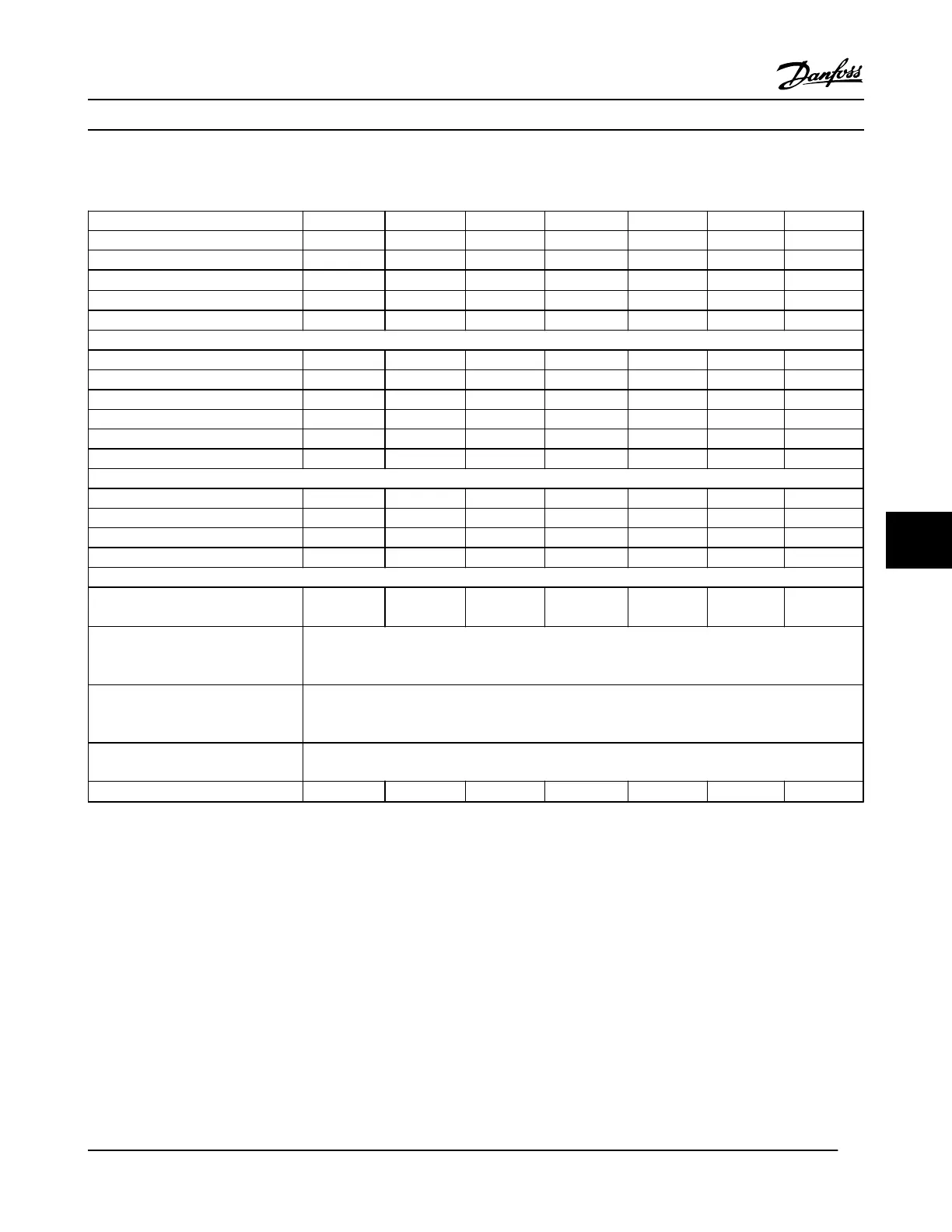
8.1.2 Line Power Supply 3x380–480 V AC
Type Designation P1K1 P1K5 P2K2 P3K0 P4K0 P5K5 P7K5
Typical Shaft Output [kW] 1.1 1.5 2.2 3.0 4.0 5.5 7.5
Typical Shaft Output [HP] at 460 V 1.5 2.0 2.9 4.0 5.0 7.5 10
IP20/Chassis
6)
A2 A2 A2 A2 A2 A3 A3
IP55/Type 12 A4/A5 A4/A5 A4/A5 A4/A5 A4/A5 A5 A5
IP66/NEMA 4X A4/A5 A4/A5 A4/A5 A4/A5 A4/A5 A5 A5
Output current
Continuous (3x380–440 V) [A] 3 4.1 5.6 7.2 10 13 16
Intermittent (3x380–440 V) [A] 3.3 4.5 6.2 7.9 11 14.3 17.6
Continuous (3x441–480 V) [A] 2.7 3.4 4.8 6.3 8.2 11 14.5
Intermittent (3x441–480 V) [A] 3.0 3.7 5.3 6.9 9.0 12.1 15.4
Continuous kVA (400 V AC) [kVA] 2.1 2.8 3.9 5.0 6.9 9.0 11.0
Continuous kVA (460 V AC) [kVA] 2.4 2.7 3.8 5.0 6.5 8.8 11.6
Max. input current
Continuous (3x380–440 V) [A] 2.7 3.7 5.0 6.5 9.0 11.7 14.4
Intermittent (3x380–440 V) [A] 3.0 4.1 5.5 7.2 9.9 12.9 15.8
Continuous (3x441–480 V) [A] 2.7 3.1 4.3 5.7 7.4 9.9 13.0
Intermittent (3x441–480 V) [A] 3.0 3.4 4.7 6.3 8.1 10.9 14.3
Additional specifications
Estimated power loss
at rated max. load [W]
4)
58 62 88 116 124 187 255
IP20, IP21 max. cable cross-section
(line power, motor, brake and load
sharing) [mm
2
/(AWG)]
2)
4, 4, 4 (12, 12, 12)
(min. 0.2 (24))
IP55, IP66 max. cable cross-section
(line power, motor, brake and load
sharing) [mm
2
/(AWG)]
2)
4, 4, 4 (12, 12, 12)
Max. cable cross-section with
disconnect
6, 4, 4 (10, 12, 12)
Efficiency
3)
0.96 0.97 0.97 0.97 0.97 0.97 0.97
Table 8.4 Line Power Supply 3x380–480 V AC - Normal overload 110% for 1 minute, P1K1-P7K5
Specifications
VLT
®
HVAC Drive Instruction Manual
MG11AJ22 - Rev. 2013-09-13 55
8 8
 Loading...


