7 Diagnostics and Troubleshooting
This chapter describes the status messages, warnings and
alarms and basic troubleshooting.
7.1 Status Messages
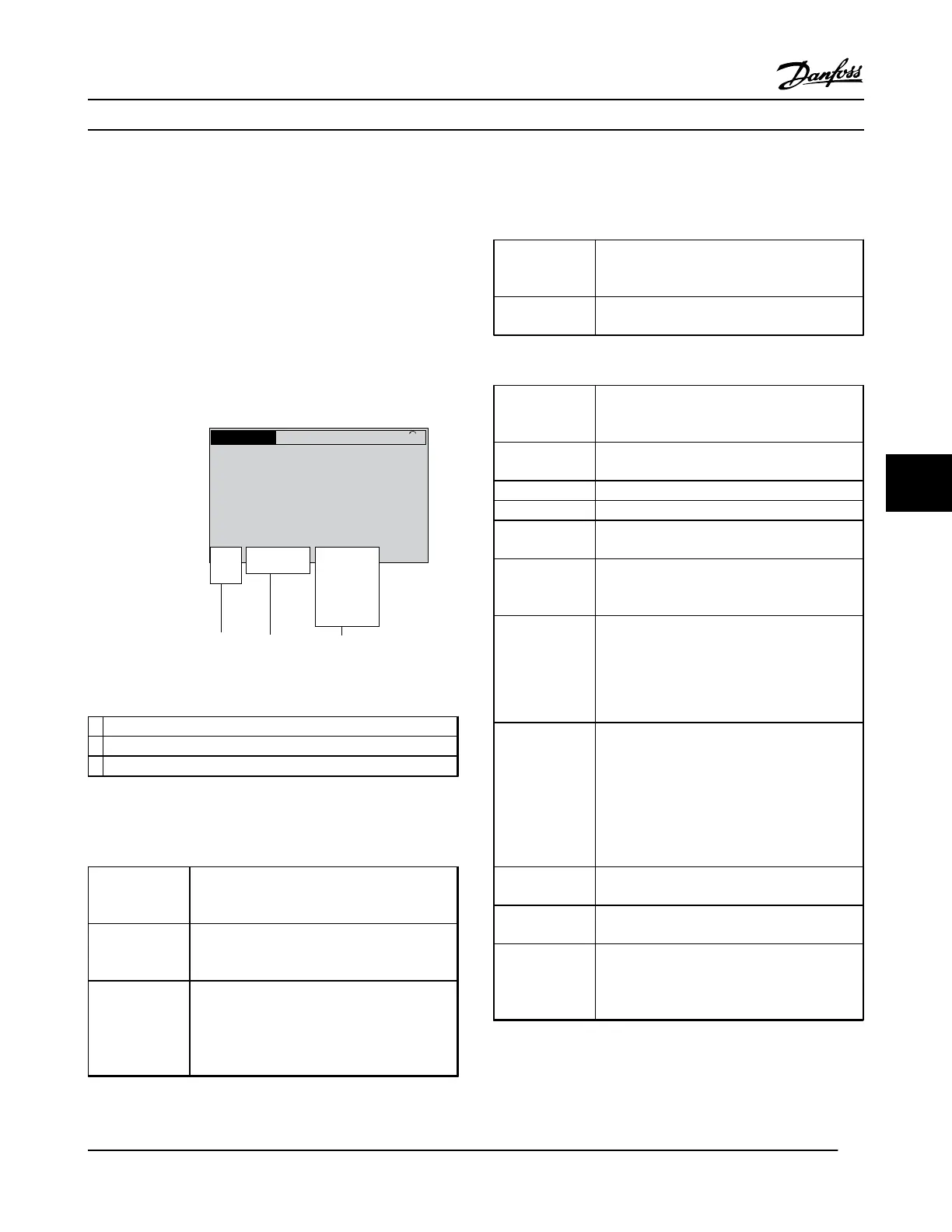
When the adjustable frequency drive is in status mode,
status messages are generated automatically and appear in
the bottom line of the display (see Figure 7.1).
Status
799RPM 7.83A 36.4kW
0.000
53.2%
1(1)
Auto
Hand
O
Remote
Local
Ramping
Stop
Running
Jogging
.
.
.
Stand by
130BB037.11
1 2 3
Figure 7.1 Status Display
1
Operation Mode (see Table 7.2)
2
Reference Site (see Table 7.3)
3
Operation Status (see Table 7.4)
Table 7.1 Legend to Figure 7.1
Table 7.2 to Table 7.4 describe the displayed status messages.
Off
The adjustable frequency drive does not react
to any control signal until [Auto On] or [Hand
On] is pressed.
Auto On The adjustable frequency drive is controlled
from the control terminals and/or the serial
communication.
The adjustable frequency drive can be
controlled by the navigation keys on the LCP.
Stop commands, reset, reversing, DC brake, and
other signals applied to the control terminals
can override local control.
Table 7.2 Operation Mode
Remote
The speed reference is given from external
signals, serial communication, or internal preset
references.
Local The adjustable frequency drive uses [Hand On]
control or reference values from the LCP.
Table 7.3 Reference Site
AC Brake
AC Brake was selected in 2-10 Brake Function.
The AC brake overmagnetizes the motor to
achieve a controlled slow-down.
AMA finish OK Automatic motor adaptation (AMA) was carried
out successfully.
AMA ready AMA is ready to start. Press [Hand On] to start.
AMA running AMA process is in progress.
Braking The brake chopper is in operation. Generative
energy is absorbed by the brake resistor.
Braking max. The brake chopper is in operation. The power
limit for the brake resistor defined in 2-12 Brake
Power Limit (kW) has been reached.
Coast
•
Coast inverse was selected as a function for
a digital input (parameter group 5-1* Digital
Inputs). The corresponding terminal is not
connected.
•
Coast activated by serial communication
Ctrl. Ramp-down
Control Ramp-down was selected in 14-10 Mains
Failure.
•
The AC line voltage is below the value set in
14-11 Mains Voltage at Mains Fault at line
power fault
•
The adjustable frequency drive ramps down
the motor using a controlled ramp-down.
Current High The adjustable frequency drive output current is
above the limit set in 4-51 Warning Current High.
Current Low The adjustable frequency drive output current is
below the limit set in 4-52 Warning Speed Low.
DC Hold
DC Hold is selected in 1-80 Function at Stop and
a stop command is active. The motor is held by
a DC current set in 2-00 DC Hold/Preheat
Current.
Diagnostics and Troubleshoo...
VLT
®
HVAC Drive Instruction Manual
MG11AJ22 - Rev. 2013-09-13 39
7 7
 Loading...


