91
L1
92
L2
93
L3
96
U
97
V
98
W
88
DC-
89
DC+
81
R-
8
R+
130BA390.11
99
95
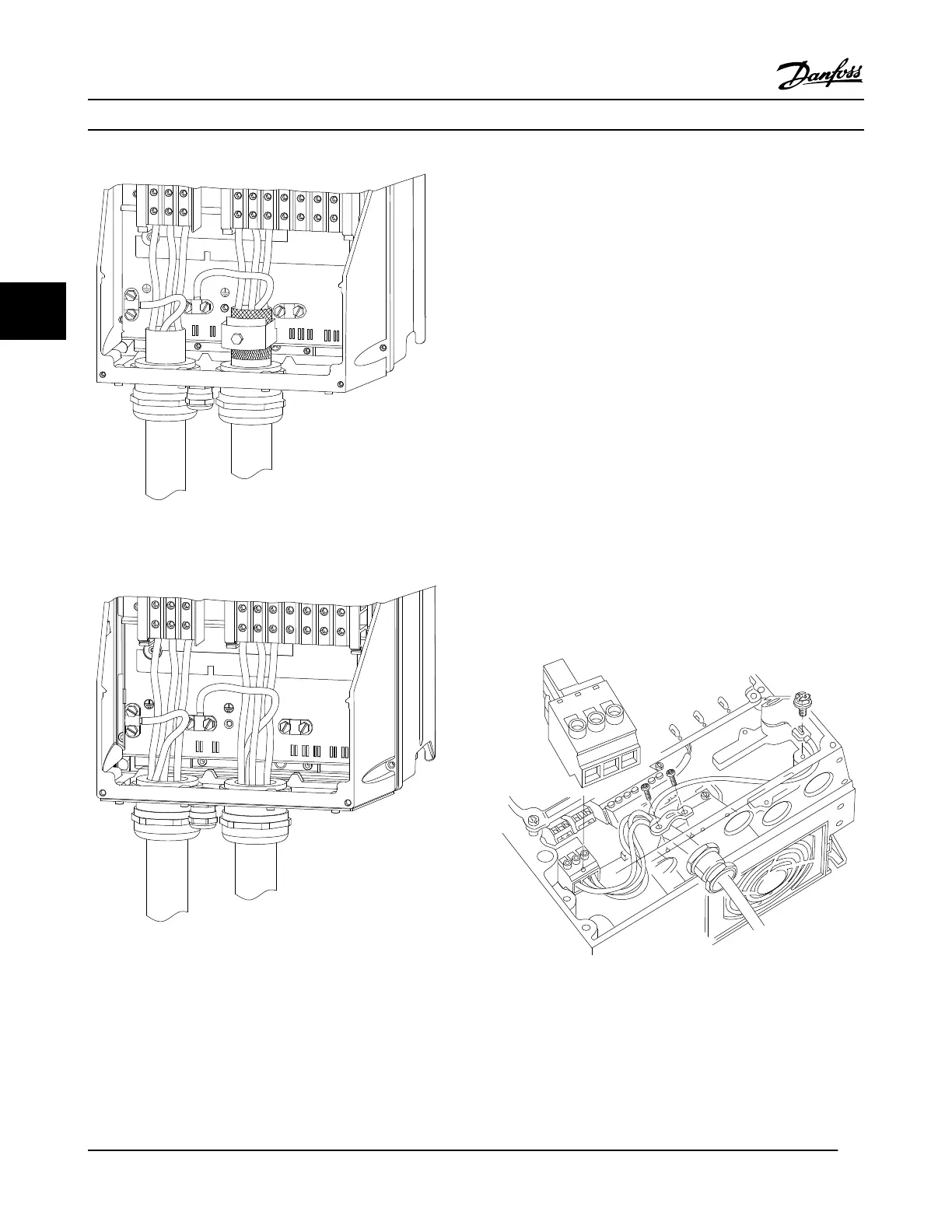
Figure 4.8 Motor, Line Power and Ground Wiring for Enclosure
Types B and C Using Shielded Cable
130BB477.10
91
L1
92
L2
93
L3
96
U
97
V
99
W
88
DC+
89
DC-
91
R-
9
R+
95
99
Figure 4.9 Motor, Line Power and Ground Wiring for Enclosure
Types B and C Using Conduit
4.7 AC Line Input Connection
•
Size wiring based upon the input current of the
adjustable frequency drive. For maximum wire sizes,
see 8.1 Electrical Data.
•
Comply with local and national electrical codes for
cable sizes.
Procedure
1. Connect 3-phase AC input power wiring to
terminals L1, L2, and L3 (see Figure 4.10).
2. Depending on the configuration of the equipment,
input power will be connected to the line power
input terminals or the input disconnect.
3. Ground the cable in accordance with grounding
instructions provided in 4.3 Grounding.
4. When supplied from an isolated line power source
(IT line power or floating delta) or TT/TN-S line
power with a grounded leg (grounded delta),
ensure that 14-50 RFI 1 is set to OFF to avoid
damage to the intermediate circuit and to reduce
ground capacity currents in accordance with IEC
61800-3.
L 1
L 2
L 3
91
92
93
130BT336.10
Figure 4.10 Connecting to AC Line Power
Electrical Installation
VLT
®
HVAC Drive Instruction Manual
18 MG11AJ22 - Rev. 2013-09-13
44
 Loading...


