•
Do not wire a starting or pole-changing device (e.g.,
Dahlander motor or slip ring induction motor)
between the adjustable frequency drive and the
motor.
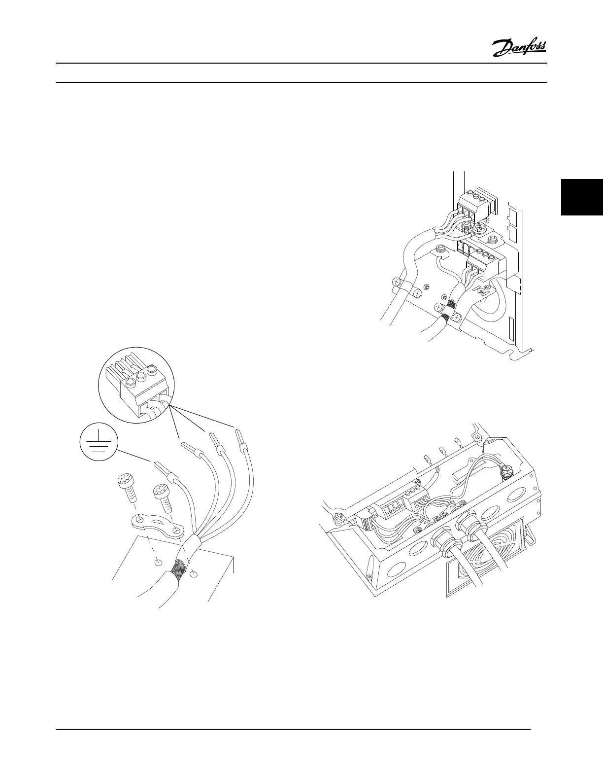
Procedure
1. Strip a section of the outer cable insulation.
2. Position the stripped wire under the cable clamp to
establish mechanical fixation and electrical contact
between cable shield and ground.
3. Connect ground wire to the nearest grounding
terminal in accordance with grounding instructions
provided in 4.3 Grounding, see Figure 4.5.
4. Connect the 3-phase motor wiring to terminals 96
(U), 97 (V), and 98 (W), see Figure 4.5.
5. Tighten terminals in accordance with the
information provided in 8.7 Connection Tightening
Torques.
Figure 4.5 Motor Connection
Figure 4.6
, Figure 4.7, Figure 4.8 and Figure 4.9 represent line
power input, motor, and grounding for basic adjustable
frequency drives. Actual configurations vary with unit types
and optional equipment.
RELAY 1 RELAY 2
99
UVW
MOTOR
Figure 4.6 Motor, Line Power and Ground Wiring for Enclosure
Types A2 and A3
Figure 4.7 Motor, Line Power and Ground Wiring for Enclosure
Types A4 and A5
Electrical Installation
VLT
®
HVAC Drive Instruction Manual
MG11AJ22 - Rev. 2013-09-13 17
4 4

 Loading...


