Warning and Alarm Displays
•
A warning is displayed in the LCP along with the
warning number.
•
An alarm flashes along with the alarm number.
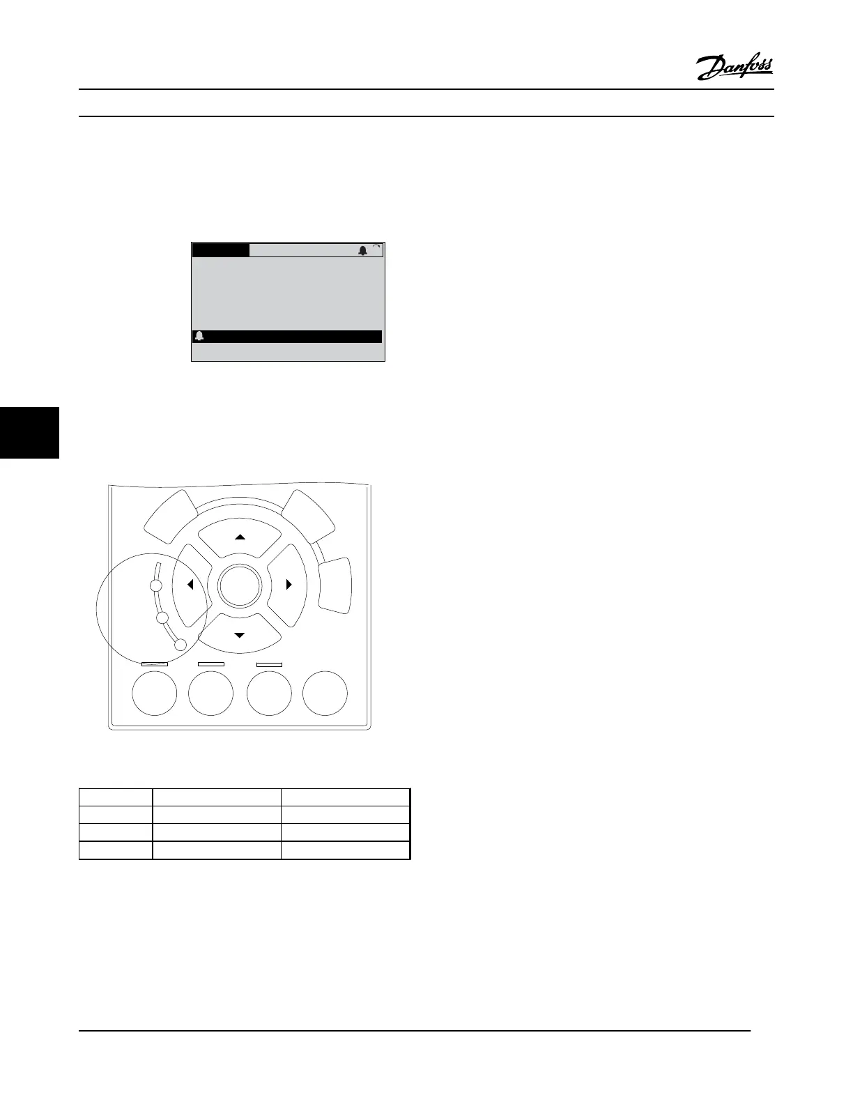
130BP086.11
Status
0.0Hz 0.000kW 0.00A
0.0Hz
0
Earth Fault [A14]
Auto Remote Trip
1(1)
Figure 7.2 Alarm Display Example
In addition to the text and alarm code on the LCP of the
adjustable frequency drive, there are three status indicator
lights.
Auto
on
Reset
Hand
on
Off
Back
Cancel
Info
OK
On
Alarm
Warn.
130BB467.10
Figure 7.3 Status Indicator Lights
Warning LED Alarm LED
Warning On Off
Alarm Off On (Flashing)
Trip Lock On On (Flashing)
Table 7.5 Status Indicator Lights Explanations
7.3
List of Warnings and Alarms
The warning/alarm information below defines each warning/
alarm condition, provides the probable cause for the
condition, and details a remedy or troubleshooting
procedure.
WARNING 1, 10 Volts low
The control card voltage is below 10 V from terminal 50.
Remove some of the load from terminal 50, as the 10 V
supply is overloaded. Max. 15 mA or minimum 590 Ω.
A short circuit in a connected potentiometer or improper
wiring of the potentiometer can cause this condition.
Troubleshooting
Remove the wiring from terminal 50. If the warning
clears, the problem is with the wiring. If the
warning does not clear, replace the control card.
WARNING/ALARM 2, Live zero error
This warning or alarm only appears if programmed in
6-01 Live Zero Timeout Function. The signal on one of the
analog inputs is less than 50% of the minimum value
programmed for that input. Broken wiring or faulty device
sending the signal can cause this condition.
Troubleshooting
Check connections on all the analog input
terminals. Control card terminals 53 and 54 for
signals, terminal 55 common. MCB 101 terminals 11
and 12 for signals, terminal 10 common. MCB 109
terminals 1, 3, 5 for signals, terminals 2, 4, 6
common).
Check that the frequency converter programming
and switch settings match the analog signal type.
Perform Input Terminal Signal Test.
WARNING/ALARM 4, Mains phase loss
A phase is missing on the supply side, or the line voltage
imbalance is too high. This message also appears for a fault
in the input rectifier on the adjustable frequency drive.
Options are programmed at 14-12 Function at Mains
Imbalance.
Troubleshooting
Check the supply voltage and supply currents to
the adjustable frequency drive.
Diagnostics and Troubleshoo...
VLT
®
HVAC Drive Instruction Manual
42 MG11AJ22 - Rev. 2013-09-13
77
 Loading...


