1.5 Block Diagram of the Adjustable
Frequency Drive
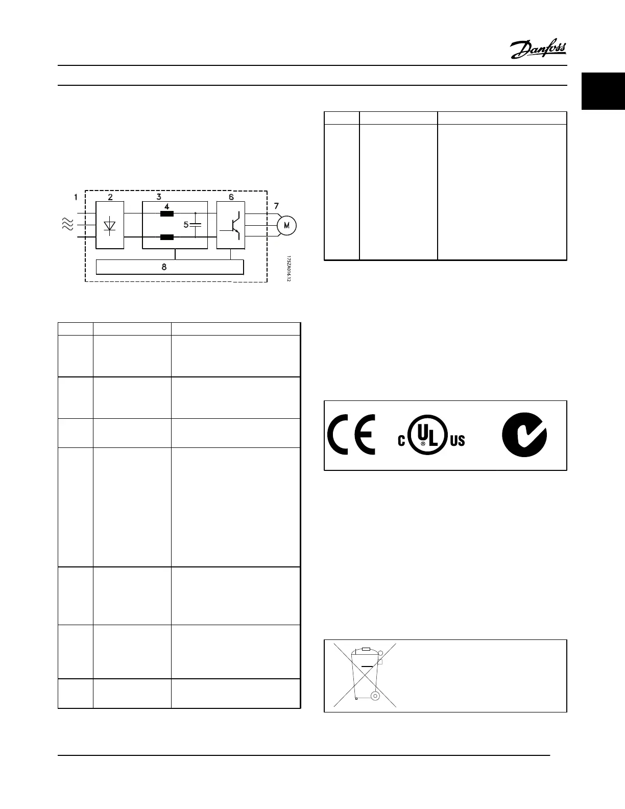
Figure 1.1 is a block diagram of the adjustable frequency
drive's internal components. See Table 1.2 for their functions.
Figure 1.1 Adjustable Frequency Drive Block Diagram
Area Title Functions
1 Line power input
•
3-phase AC line power supply
to the adjustable frequency
drive
2 Rectifier
•
The rectifier bridge converts
the AC input to DC current to
supply inverter power
3 DC bus
•
Intermediate DC bus circuit
handles the DC current
4 DC reactors
•
Filter the intermediate DC
circuit voltage
•
Prove line transient protection
•
Reduce RMS current
•
Raise the power factor
reflected back to the line
•
Reduce harmonics on the AC
input
5 Capacitor bank
•
Stores the DC power
•
Provides ride-through
protection for short power
losses
6 Inverter
•
Converts the DC into a
controlled PWM AC waveform
for a controlled variable output
to the motor
7 Output to motor
•
Regulated 3-phase output
power to the motor
Area Title Functions
8 Control circuitry
•
Input power, internal
processing, output, and motor
current are monitored to
provide efficient operation and
control
•
User interface and external
commands are monitored and
performed
•
Status output and control can
be provided
Table 1.2 Legend to Figure 1.1
1.6 Enclosure Types and Power Ratings
For enclosure types and power ratings of the adjustable
frequency drives, refer to 8.9 Power Ratings, Weight and
Dimensions.
1.7 Approvals and Certifications
Table 1.3 Approvals and Certifications
More approvals and certifications are available. Contact local
Danfoss partner. The T7 (525–690 V) adjustable frequency
drives are not certified for UL.
The adjustable frequency drive complies with UL508C
thermal memory retention requirements. For more
information, refer to the section Motor Thermal Protection in
the Design Guide.
1.8
Disposal Instruction
Do not dispose of equipment containing
electrical components together with
domestic waste.
Collect it separately in accordance with
local and currently valid legislation.
Table 1.4 Disposal Instruction
Introduction
VLT
®
HVAC Drive Instruction Manual
MG11AJ22 - Rev. 2013-09-13 5
1
1

 Loading...


