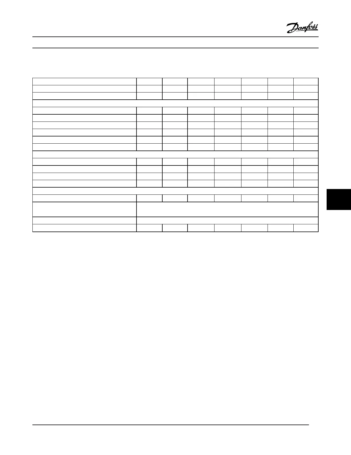
8.1.4 Line Power Supply 3 x 525–690 V AC
Type Designation P1K1 P1K5 P2K2 P3K0 P4K0 P5K5 P7K5
Typical Shaft Output [kW] 1.1 1.5 2.2 3.0 4.0 5.5 7.5
Enclosure IP20 (only) A3 A3 A3 A3 A3 A3 A3
Output current
Continuous (3 x 525–550 V) [A] 2.1 2.7 3.9 4.9 6.1 9.0 11
Intermittent (3 x 525–550 V) [A] 3.4 4.3 6.2 7.8 9.8 14.4 17.6
Continuous kVA (3 x 551–690 V) [A] 1.6 2.2 3.2 4.5 5.5 7.5 10
Intermittent kVA (3 x 551–690 V) [A] 2.6 3.5 5.1 7.2 8.8 12 16
Continuous kVA 525 V AC 1.9 2.5 3.5 4.5 5.5 8.2 10
Continuous kVA 690 V AC 1.9 2.6 3.8 5.4 6.6 9.0 12
Max. input current
Continuous (3 x 525–550 V) [A] 1.9 2.4 3.5 4.4 5.5 8.0 10
Intermittent (3 x 525–550 V) [A] 3.0 3.9 5.6 7.1 8.8 13 16
Continuous kVA (3 x 551–690 V) [A] 1.4 2.0 2.9 4.0 4.9 6.7 9.0
Intermittent kVA (3 x 551–690 V) [A] 2.3 3.2 4.6 6.5 7.9 10.8 14.4
Additional specifications
Estimated power loss at rated max. load [W] 4) 44 60 88 120 160 220 300
Max. cable cross-section
5)
(line power, motor, brake
and load sharing) [mm
2
]/(AWG)
6, 4, 4 (10, 12, 12)
(min. 0.2 (24))
Max. cable cross-section with disconnect 6, 4, 4 (10, 12, 12)
Efficiency
3)
0.96 0.96 0.96 0.96 0.96 0.96 0.96
Table 8.8 Line Power Supply 3x525–690 V AC - Normal overload 110% for 1 minute, P1K1-P7K5
Specifications
VLT
®
HVAC Drive Instruction Manual
MG11AJ22 - Rev. 2013-09-13 59
8 8
 Loading...


