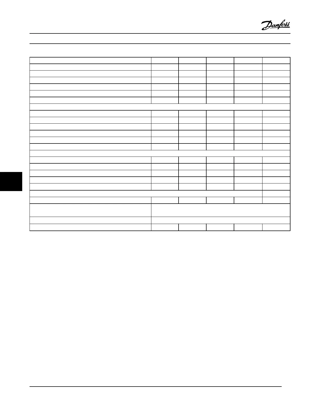
Type Designation P11K P15K P18K P22K P30K
High/Normal Load NO NO NO NO NO
Typical Shaft Output at 550 V [kW] 7.5 11 15 18.5 22
Typical Shaft Output at 690 V [kW] 11 15 18.5 22 30
IP20/Chassis B4 B4 B4 B4 B4
IP21/NEMA 1 B2 B2 B2 B2 B2
IP55/NEMA 12 B2 B2 B2 B2 B2
Output current
Continuous (3 x 525–550 V) [A] 14 19 23 28 36
Intermittent (60 s overload) (3 x 525–550 V) [A] 22.4 20.9 25.3 30.8 39.6
Continuous (3 x 551–690 V) [A] 13 18 22 27 34
Intermittent (60 s overload) (3 x 551–690 V) [A] 20.8 19.8 24.2 29.7 37.4
Continuous kVA (550 V AC) [kVA] 13.3 18.1 21.9 26.7 34.3
Continuous kVA (690 V AC) [kVA] 15.5 21.5 26.3 32.3 40.6
Max. input current
Continuous (at 550 V) [A] 15 19.5 24 29 36
Intermittent (60 s overload) (at 550 V) [A] 23.2 21.5 26.4 31.9 39.6
Continuous (at 690 V) [A] 14.5 19.5 24 29 36
Intermittent (60 s overload) (at 690 V) [A] 23.2 21.5 26.4 31.9 39.6
Max. pre-fuses
1)
[A]
63 63 63 80 100
Additional specifications
Estimated power loss at rated max. load [W] 4) 150 220 300 370 440
Max. cable cross-section (line power/motor, load sharing and
brake) [mm
2
]/(AWG)
2)
35, 25, 25 (2, 4, 4)
Max. cable size with line power disconnect [mm
2
]/(AWG)
2)
16, 10, 10 (6, 8, 8)
Efficiency
3)
0.98 0.98 0.98 0.98 0.98
Table 8.9 Line Power Supply 3 x 525–690 V AC - Normal overload 110% for 1 minute, P11K-P30K
Specifications
VLT
®
HVAC Drive Instruction Manual
60 MG11AJ22 - Rev. 2013-09-13
88

 Loading...


