6 Application Set-up Examples
The examples in this section are intended as a quick
reference for common applications.
•
Parameter settings are the regional default values
unless otherwise indicated (selected in
0-03 Regional Settings).
•
Parameters associated with the terminals and their
settings are shown next to the drawings.
•
Where switch settings for analog terminals A53 or
A54 are required, these are also shown.
NOTICE!
When the optional Safe Torque Off feature is used, a
jumper wire may be required between terminal 12 (or 13)
and terminal 37 for the adjustable frequency drive to
operate when using factory default programming values.
6.1 Application Examples
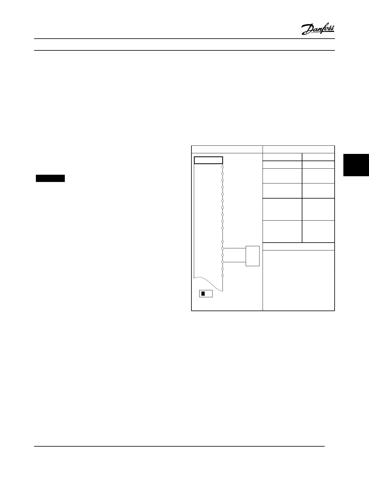
6.1.1 Speed
Parameters
FC
+24 V
+24 V
D IN
D IN
D IN
COM
D IN
D IN
D IN
D IN
+10
A IN
A IN
COM
A OUT
COM
12
13
18
19
20
27
29
32
33
37
50
53
54
55
42
39
A53
U - I
-10 - +10V
+
-
130BB926.10
Function Setting
6-10 Terminal 53
Low Voltage
0.07 V*
6-11 Terminal 53
High Voltage
10 V*
6-14 Terminal 53
Low Ref./Feedb.
Value
0 RPM
6-15 Terminal 53
High Ref./Feedb.
Value
1500 RPM
* = Default Value
Notes/comments:
D IN 37 is an option.
Table 6.1 Analog Speed Reference (Voltage)
Application Set-up Examples
VLT
®
HVAC Drive Instruction Manual
MG11AJ22 - Rev. 2013-09-13 33
6 6
 Loading...


