5.4 Basic Programming
5.4.1 Commissioning with SmartStart
The SmartStart wizard enables fast configuration of basic
motor and application parameters.
•
At first power-up or after initialization of the
adjustable frequency drive, SmartStart starts by
itself.
•
Follow on-screen instructions to complete commis-
sioning of the adjustable frequency drive.
SmartStart can always be reactivated by selecting
Quick Menu Q4 - SmartStart.
•
For commissioning without use of the SmartStart
wizard, refer to 5.4.2 Commissioning via [Main Menu]
or the Programming Guide.
NOTICE!
Motor data are required for the SmartStart set-up. The
required data are normally available on the motor
nameplate.
5.4.2 Commissioning via [Main Menu]
Recommended parameter settings are intended for start-up
and checkout purposes. Application settings may vary.
Enter data with power ON, but before operating the
adjustable frequency drive.
1. Press [Main Menu] on the LCP.
2. Use the navigation keys to scroll to parameter
group 0-** Operation/Display and press [OK].
130BP066.10
1107 RPM
0 - ** Operation/Display
1 - ** Load/Motor
2 - ** Brakes
3 - ** Reference / Ramps
3.84 A 1 (1)
Main Menu
Figure 5.2 Main Menu
3. Use navigation keys to scroll to parameter group
0-0* Basic Settings and press [OK].
0-
**
Operation / Display
0.0%
0-0
*
Basic Settings
0-1
*
Set-up Operations
0-2
*
LCP Display
0-3
*
LCP Custom Readout
0.00A 1(1)
130BP087.10
Figure 5.3 Operation/Display
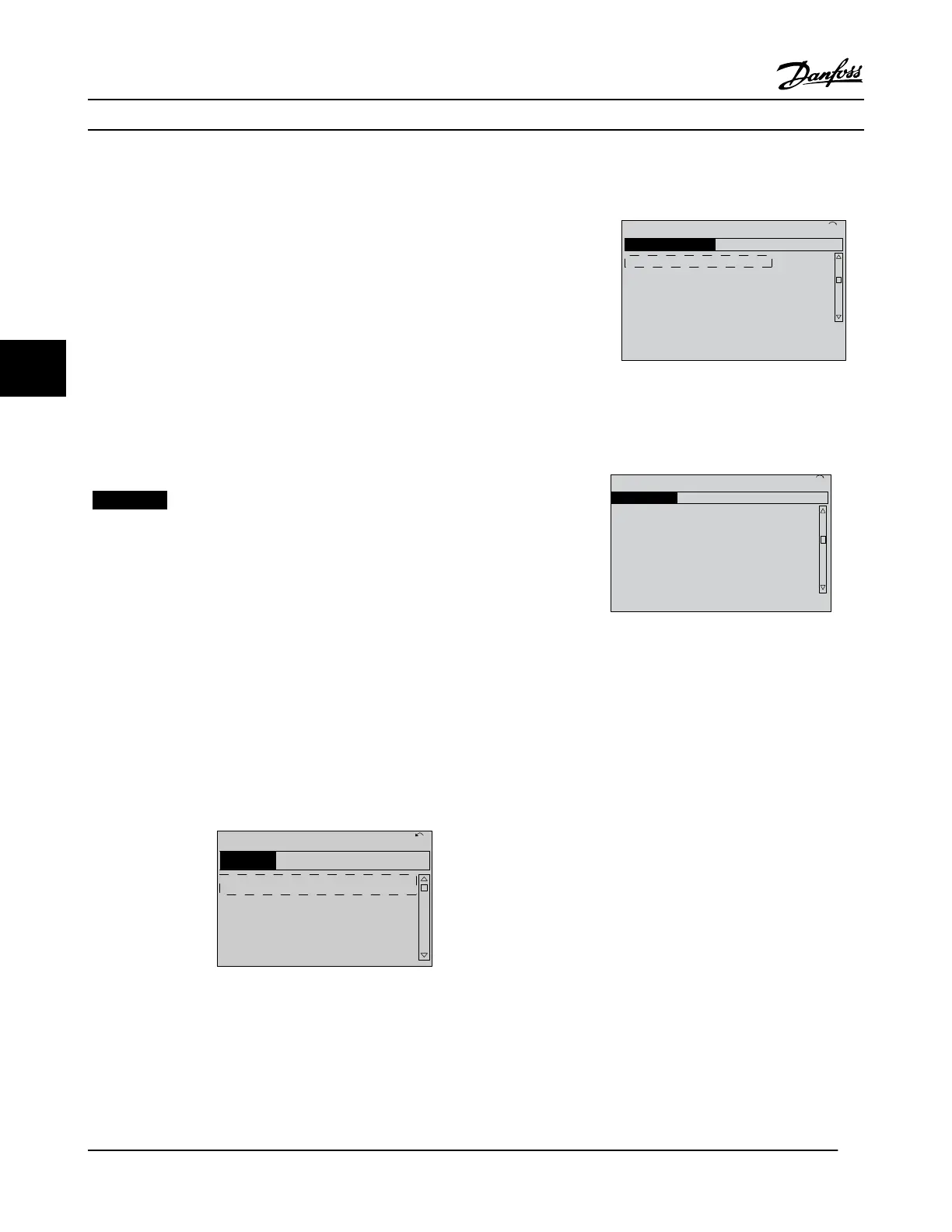
4.
Use navigation keys to scroll to 0-03 Regional
Settings and press [OK].
0-0
*
Basic Settings
0.0%
0-03 Regional Settings
[0] International
0.00A 1(1)
130BP088.10
Figure 5.4 Basic Settings
5.
Use navigation keys to select [0] International or [1]
North America as appropriate and press [OK]. (This
changes the default settings for a number of basic
parameters).
6. Press [Main Menu] on the LCP.
7.
Use the navigation keys to scroll to 0-01 Language.
8. Select language and press [OK].
9. If a jumper wire is in place between control
terminals 12 and 27, leave 5-12 Terminal 27 Digital
Input at factory default. Otherwise, No Operation
should be selected in 5-12 Terminal 27 Digital Input.
For adjustable frequency drives with an optional
bypass, no jumper wire is required between control
terminals 12 and 27.
10.
3-02 Minimum Reference
11.
3-03 Maximum Reference
Commissioning
VLT
®
HVAC Drive Instruction Manual
28 MG11AJ22 - Rev. 2013-09-13
55

 Loading...


