Analog inputs
Number of analog inputs 2
Terminal number 53, 54
Modes Voltage or current
Mode select Switch S201 and switch S202
Voltage mode Switch S201/switch S202 = OFF (U)
Voltage level -10 to +10 V (scalable)
Input resistance, R
i
approx. 10 kΩ
Max. voltage ±20 V
Current mode Switch S201/switch S202 = ON (I)
Current level 0/4 to 20 mA (scalable)
Input resistance, R
i
approx. 200 Ω
Max. current 30 mA
Resolution for analog inputs 10 bit (+ sign)
Accuracy of analog inputs Max. error 0.5% of full scale
Bandwidth 20 Hz/100 Hz
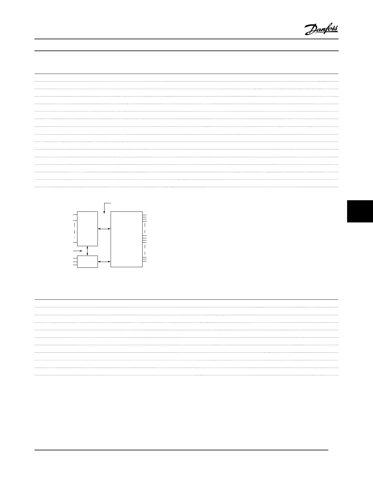
The analog inputs are galvanically isolated from the supply voltage (PELV) and other high-voltage terminals.
Mains
Functional
isolation
PELV isolation
Motor
DC-Bus
High
voltage
Control
+24V
RS485
18
37
130BA117.10
Figure 8.1 PELV Isolation
Pulse
Programmable pulse 2/1
Terminal number pulse 29
1)
, 33
2)
/ 33
3)
Max. frequency at terminal 29, 33 110 kHz (push-pull driven)
Max. frequency at terminal 29, 33 5 kHz (open collector)
Min. frequency at terminal 29, 33 4 Hz
Voltage level see 8.6.1 Digital Inputs
Maximum voltage on input 28 V DC
Input resistance, R
i
approx. 4 kΩ
Pulse input accuracy (0.1–1 kHz) Max. error: 0.1% of full scale
Encoder input accuracy (1–11 kHz) Max. error: 0.05% of full scale
The pulse and encoder inputs (terminals 29, 32, 33) are galvanically isolated from the supply voltage (PELV) and other high-voltage
terminals.
1)
FC 302 only
2)
Pulse inputs are 29 and 33
Specifications
VLT
®
HVAC Drive Instruction Manual
MG11AJ22 - Rev. 2013-09-13 65
8 8
 Loading...


