Example of programming the speed control
In this example, the speed PID control is used to maintain a constant motor speed regardless of the changing load on the
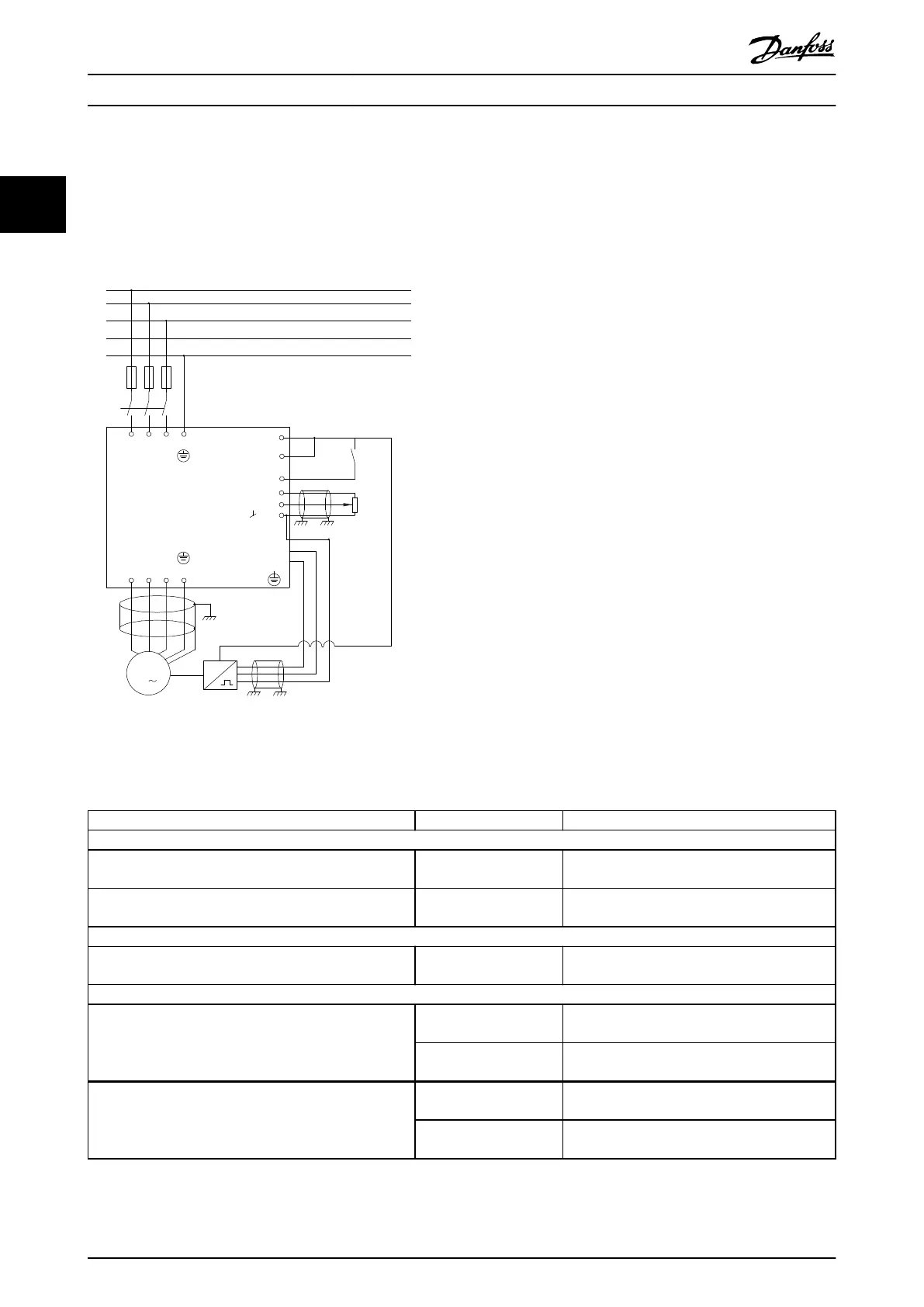
motor. The required motor speed is set via a potentiometer connected to terminal 53. The speed range is 0–1500 RPM
corresponding to 0–10 V over the potentiometer. A switch connected to terminal 18 controls starting and stopping. The
speed PID monitors the actual RPM of the motor by using a 24 V (HTL) incremental encoder as feedback. The feedback
sensor is an encoder (1024 pulses per revolution) connected to terminals 32 and 33. The pulse frequency range to terminals
32 and 33 is 4 Hz–32 kHz.
M
3
96 97 9998
91 92 93 95
50
12
L1 L2
L1
PEL3
W PEVU
F1
L2
L3
N
PE
18
53
27
55
32
33
24 Vdc
130BD372.11
Illustration 2.21 Speed Control Programming
Follow the steps in Table 2.7 to program the speed control (see explanation of settings in the programming guide)
In Table 2.7, it is assumed that all other parameters and switches remain at their default setting.
Function Parameter number Setting
1) Make sure that the motor runs properly. Do the following:
Set the motor parameters using the data on the
nameplate.
1-2* Motor Data As specied by motor nameplate.
Perform an AMA. Parameter 1-29 Automatic
Motor Adaption (AMA)
[1] Enable complete AMA
2) Check that the motor is running and that the encoder is attached properly. Do the following:
Press [Hand On]. Check that the motor is running and note
the rotation direction (referred to as the positive direction).
Set a positive reference.
3) Make sure that the frequency converter limits are set to safe values:
Set acceptable limits for the references. Parameter 3-02 Minimum
Reference
0
Parameter 3-03 Maximum
Reference
50
Check that the ramp settings are within frequency
converter capabilities and allowed application operating
specications.
Parameter 3-41 Ramp 1
Ramp Up Time
Default setting
Parameter 3-42 Ramp 1
Ramp Down Time
Default setting
Product Overview
VLT
®
Midi Drive FC 280
28 Danfoss A/S © 03/2016 All rights reserved. MG07B102
22
 Loading...


