Do you have a question about the Datacom DM4001 and is the answer not in the manual?
Guide covers installation and characteristics of DATACOM DM4000 Metro Ethernet Series.
DM4000 Metro Ethernet Series offers reliable Fast, Gigabit, and 10 Gigabit Ethernet solutions.
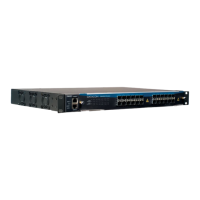
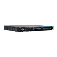
The DM4001 chassis is compatible with all DM4000 series interface boards for stand-alone versions.
Describes the RS232 console port, Ethernet outband management interface, and status LEDs on the front panel.
Explains the system status LEDs on the front panel used to monitor system activity.
Details the two RJ-45 connectors on the front panel for console and outband management.
Covers the rear panel of the DM4001 chassis, including DC input power connectors.
The DM4004 chassis supports up to 384Gbps non-blocking data with four interface, two MPU, and FAN slots.
Describes the front panel of the DM4004 chassis, noting the main input power connectors.
Details the rear panel of the DM4004 chassis.
The DM4008 chassis supports up to 384Gbps non-blocking data with eight interface, two MPU, and FAN slots.
Describes the front panel of the DM4008 chassis, noting the main input power connectors.
Details the rear panel of the DM4008 chassis.
The DM4000 MPU192 is a hot-swappable Switch Fabric capable of handling 192Gbps of Non-blocking Data.
Details the front panel of the MPU192, including System Status LEDs and management ports.
Explains the 9 system status LEDs monitoring CPU utilization, Ethernet Outband, and MPU status.
Covers the three RJ-45 connectors on the front panel for management and console ports.
The DM4000 MPU384 is a hot-swappable Switch Fabric capable of handling 384Gbps of Non-blocking Data.
Details the front panel of the MPU384, including System Status LEDs and management ports.
Explains the 9 system status LEDs monitoring CPU utilization, Ethernet Outband, and MPU status.
Covers the three RJ-45 connectors on the front panel for management and console ports.
A non-blocking 24-port SFP interface board compatible with DM4001, DM4004, and DM4008 chassis.
Describes the front panel, highlighting SFP ports and Port Status LEDs.
Details the port LED status for the DM4000 ETH24GX-MPLS.
Lists software and hardware specifications for the DM4000 ETH24GX-MPLS.
A non-blocking 12-port SFP interface board compatible with DM4001, DM4004, and DM4008 chassis.
Describes the front panel, highlighting SFP ports and Port Status LEDs.
Details the port LED status for the DM4000 ETH12GX-MPLS.
Lists software and hardware specifications for the DM4000 ETH12GX-MPLS.
A non-blocking 12-port SFP plus one 10 Gigabit XFP port interface board.
Describes the front panel, highlighting SFP, XFP ports, and Port Status LEDs.
Details the port LED status for the DM4000 ETH12GX+1x10GX-MPLS.
Lists software and hardware specifications for the DM4000 ETH12GX+1x10GX-MPLS.
A non-blocking two 10 Gigabit XFP port interface board compatible with DM4001, DM4004, DM4008.
Describes the front panel, highlighting SFP, XFP ports, and Port Status LEDs.
Details the port LED status for the DM4000 ETH2x10GX-MPLS.
Lists software and hardware specifications for the DM4000 ETH2x10GX-MPLS.
A non-blocking 24-port 1000/100/10 Mbps interface board compatible with DM4001, DM4004, DM4008.
Describes the front panel, containing 24 RJ45 Ports and their Port Status LEDs.
Details the port status LEDs for the DM4000 ETH24GT.
Lists software and hardware specifications for the DM4000 ETH24GT.
A non-blocking 48-port 1000/100/10 Mbps interface board compatible with DM4001, DM4004, DM4008.
Describes the front panel, containing 48 RJ45 Ports and their Port Status LEDs.
Details the port status LEDs for the DM4000 ETH48GT.
Lists software and hardware specifications for the DM4000 ETH48GT.
Explains the function of fan boards for temperature regulation and hot-swappable replacement.
Instructions for installing the switch in a 19" rack using provided brackets.
Guide on connecting the power cable and verifying the power LED status.
Procedures for installing a fan board into the switch chassis.
Instructions on correctly inserting an interface board into the DM4004 or DM4008 chassis.
Step-by-step guide for installing an SFP transceiver into a switch module bay.
Instructions for safely removing SFP modules from the switch, including warnings.
Details operating and storage temperature, and humidity specifications.
Provides DC voltage range and power consumption details for various components.
Lists the height, width, and depth specifications for different chassis models.
Provides weight specifications for chassis, MPUs, and interface boards in kilograms and pounds.
Lists various IEEE, IETF, Safety, EMI, and Environmental norms and certifications.
Details the pin order for DB9 connectors and the RJ45-DB9 pin mapping.
| Brand | Datacom |
|---|---|
| Model | DM4001 |
| Category | Network Router |
| Language | English |