Do you have a question about the Datacom DM4000 Series and is the answer not in the manual?
Provides essential safety and preparatory steps before installing the equipment.
Explains the purpose and scope of the guide for DM4000 Metro Ethernet Series.
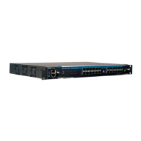
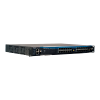
Introduces the DM4000 Metro Ethernet Switches and their chassis/interface module models.
Details operating and storage temperature, and humidity requirements for the equipment.
Covers DC power input range and related warnings for the DM4000 family.
Describes the DM4001 chassis, its compatibility, and backplane interface features.
Details the components on the DM4001 chassis front panel, including ports and LEDs.
Explains the system status LEDs on the DM4001 chassis and their meanings.
Describes the Console and Outband Management ports on the DM4001 chassis.
Details the rear panel of the DM4001 chassis, including power inputs.
Introduces the DM4004 chassis, its rack versions, and slot configurations.
Describes the front panel of the DM4004 chassis, focusing on power input connectors.
Details the rear panel of the DM4004 chassis, noting the console DB9 connector.
Explains the console management port on the DM4004 chassis and its pinouts.
Describes the DM4008 chassis, its compatibility, and slot configurations.
Details the front panel of the DM4008 chassis, including power input connectors.
Details the rear panel of the DM4008 chassis, noting the console DB9 connector.
Explains the console management port on the DM4008 chassis and its pinouts.
Introduces the DM4000 MPU192, its capabilities, and compatibility with chassis.
Describes the DM4000 MPU192 front panel components, including LEDs and ports.
Explains the system status LEDs on the DM4000 MPU192 front panel.
Details the Console and Outband Management ports on the DM4000 MPU192.
Introduces the DM4000 MPU384, its capabilities, and compatibility with chassis.
Describes the DM4000 MPU384 front panel components, including LEDs and ports.
Explains the system status LEDs on the DM4000 MPU384 front panel.
Details the Console and Outband Management ports on the DM4000 MPU384.
Introduces the DM4000 MPU416, its capabilities, and compatibility with chassis.
Describes the DM4000 MPU416 front panel components, including LEDs and ports.
Explains the system status LEDs on the DM4000 MPU416 front panel.
Details the Console and Outband Management ports on the DM4000 MPU416.
Introduces the DM4000 ETH24GX interface board and its specifications.
Describes the front panel of the DM4000 ETH24GX, including SFP slots and LEDs.
Explains the port status LEDs on the DM4000 ETH24GX interface board.
Details the software and hardware features of the DM4000 ETH24GX.
Introduces the DM4000 ETH24GX H Series interface board and its specifications.
Describes the front panel of the DM4000 ETH24GX H Series, including SFP slots and LEDs.
Explains the port status LEDs on the DM4000 ETH24GX H Series interface board.
Details the software and hardware features of the DM4000 ETH24GX H Series.
Introduces the DM4000 ETH12GX interface board and its specifications.
Describes the front panel of the DM4000 ETH12GX, including SFP slots and LEDs.
Explains the port status LEDs on the DM4000 ETH12GX interface board.
Details the software and hardware features of the DM4000 ETH12GX.
Introduces the DM4000 ETH12GX+1x10GX board and its specifications.
Describes the front panel of the DM4000 ETH12GX+1x10GX board, ports, and LEDs.
Explains the port status LEDs on the DM4000 ETH12GX+1x10GX board.
Details the software and hardware features of the DM4000 ETH12GX+1x10GX.
Introduces the DM4000 ETH2x10GX interface board and its specifications.
Describes the front panel of the DM4000 ETH2x10GX, including XFP ports and LEDs.
Explains the port status LEDs on the DM4000 ETH2x10GX interface board.
Details the software and hardware features of the DM4000 ETH2x10GX.
Introduces the DM4000 ETH24GT interface board and its specifications.
Describes the front panel of the DM4000 ETH24GT, including RJ45 ports and LEDs.
Explains the port status LEDs on the DM4000 ETH24GT interface board.
Details the software and hardware features of the DM4000 ETH24GT.
Introduces the DM4000 ETH48GT interface board and its specifications.
Describes the front panel of the DM4000 ETH48GT, including RJ45 ports and LEDs.
Explains the port status LEDs on the DM4000 ETH48GT interface board.
Details the software and hardware features of the DM4000 ETH48GT.
Introduces the DM4000 ETH48GX H Series board and its specifications.
Describes the front panel of the DM4000 ETH48GX H Series, including SFP slots and LEDs.
Explains the port status LEDs on the DM4000 ETH48GX H Series board.
Details the software and hardware features of the DM4000 ETH48GX H Series.
Introduces the DM4000 ETH24GX+2x10GX H Series board and its specifications.
Describes the front panel of the DM4000 ETH24GX+2x10GX H Series, ports, and LEDs.
Explains the port status LEDs on the DM4000 ETH24GX+2x10GX H Series board.
Details the software and hardware features of the DM4000 ETH24GX+2x10GX H Series.
Introduces the DM4000 ETH2x10GX H Series board and its specifications.
Describes the front panel of the DM4000 ETH2x10GX H Series, ports, and LEDs.
Explains the port status LEDs on the DM4000 ETH2x10GX H Series board.
Details the software and hardware features of the DM4000 ETH2x10GX H Series.
Introduces the DM4000 ETH4x10GX H Series board and its specifications.
Describes the front panel of the DM4000 ETH4x10GX H Series, ports, and LEDs.
Explains the port status LEDs on the DM4000 ETH4x10GX H Series board.
Details the software and hardware features of the DM4000 ETH4x10GX H Series.
Introduces the DM4000 GPC-OAB active booster amplifier and its function.
Describes the front panel of the DM4000 GPC-OAB, including status LEDs.
Introduces the DM4000 GPC-OAP active pre-amplifier and its function.
Describes the front panel of the DM4000 GPC-OAP, including status LEDs.
Introduces the DM4000 GPC-DCM Dispersion-compensating Module and its function.
Describes the front panel of the DM4000 GPC-DCM, including connectors.
Explains the purpose and hot-swappable nature of the FAN module.
Illustrates the air flow patterns within the DM4004 and DM4008 chassis.
Details the components included in the DM4004 and DM4008 installation kit.
Provides instructions and warnings for powering the switch and connecting cables.
Details cable dimensions and build information for power supply connections.
Provides instructions for installing the FAN module into the chassis.
Provides instructions for removing the FAN module from the chassis.
Illustrates the correct procedure for inserting interface boards into the chassis.
Covers the installation and removal of SFP modules.
Step-by-step guide on how to connect an optical SFP module to an interface board.
Provides instructions for removing SFP modules from the interface board.
Explains DATACOM's checks for homologated transceivers and potential risks.
Details how to build a DB9-RJ45 cable for serial port communication.
Guides on connecting optical amplifiers (EDFA) to interface boards for signal amplification.
Lists applicable EMC, EMI, and Safety standards for the DM4000 family.
| Model | DM4000 Series |
|---|---|
| Category | Network Router |
| Ports | Varies by model (e.g., Gigabit Ethernet, SFP+) |
| Dimensions | Varies by model |
| Weight | Varies by model |
| Operating Temperature | 0°C to 40°C |
| Storage Temperature | -20°C to 70°C |