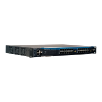
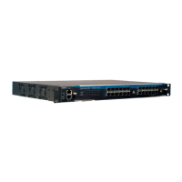
Chapter 4. DM4001 Chassis
Table 4-1. System LEDs DM4001 Chassis
LED CONDITION STATUS
Power ON Equipment on.
OFF Equipment off.
Fail ON Indicates fail (high temperature or fan fail).
OFF Equipment operates normally.
Link/Act ON/Blinking Connected with link up. Blinking indicates
activity.
OFF No connection established.
Speed ON 10Mbit/s connection established.
OFF Indicates a 100Mbit/s Connection when Link/Act
LED is ON or Blinking.
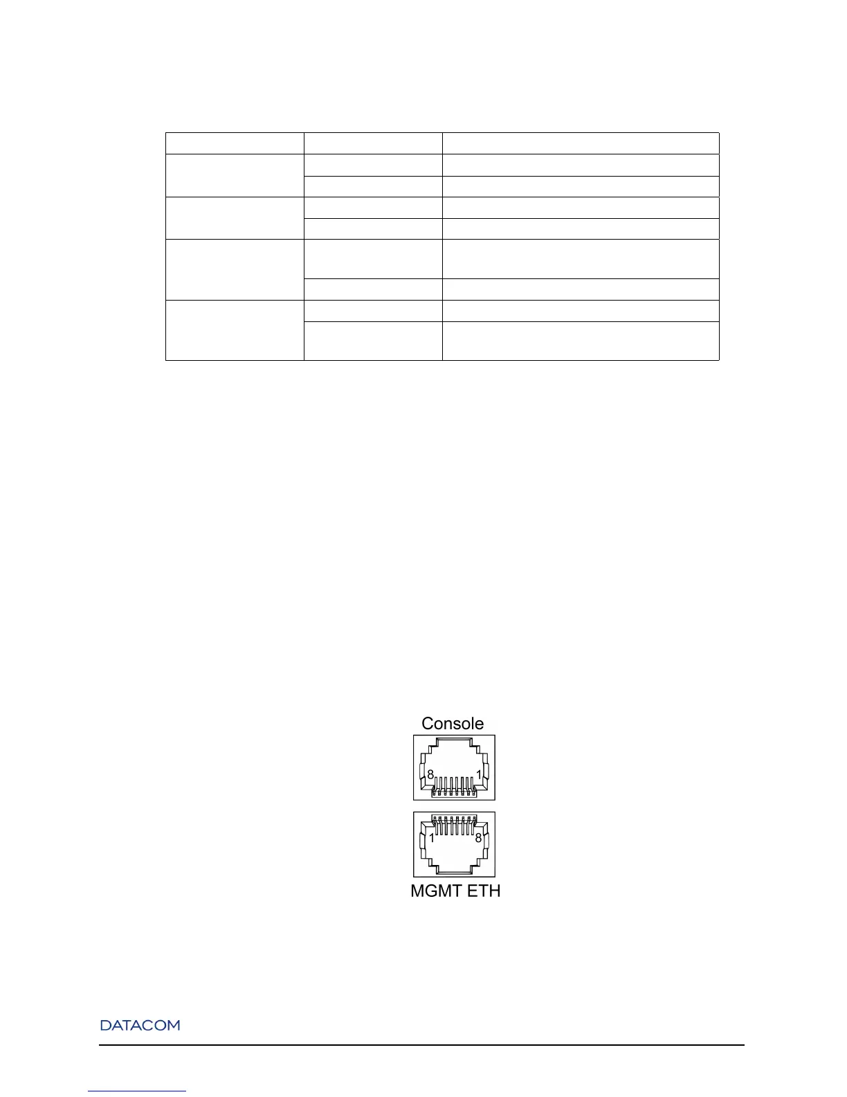
4.4. Console and Ethernet Outband Management Ports
The switch contains two RJ-45 connectors on its front panel. The upper connector is the Console port and
the lower is the Outband Management port.
The Management port can be connected to a desktop through a CAT 5 Ethernet cable.
The pinouts of both Console and Outband Management ports are shown in the following figure and table.
Figure 4-4. Double RJ-45 Connector
15
 Loading...