Chapter 2. DM4001 Chassis
2.3. System Status Leds
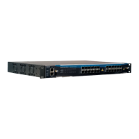
The System Status LEDs on the front panel can be used to monitor system activity. Following Figure
shows where the leds are located and the table below indicates the system status acording to each led’s
condition.
Figure 2-3. DM4001 Chassis - Front Panel Leds
Table 2-1. System LEDs DM4001 Chassis
LED CONDITION STATUS
Power ON Equipment on.
OFF Equipment off.
Fail ON Indicates fail (high temperature or fan fail).
OFF Equipment runs normally.
Link/Act ON/Blinking Connected in link up. Blinking indicates
activity.
OFF No connection established.
Speed ON No 100Mbit/s connection established.
OFF Indicates 100Mbit/s link.
2.4. Console and Ethernet Outband Management Ports
The switch contains two RJ-45 connectors on its front panel. The upper connector is the console port and
the lower is the Outband Management port.
The Management interface can be connected to a desktop throught a CAT 5 ethernet cable and the console
cable pinout to a standard DB9 connector can be found in the appendix A.
4