Edit Configuration – Advanced – PLC Logic
111
4.15.2.6 CREATING AND EDITING RUNGS
• Click a symbol in the tool bar and drag it to the bar ( )
to create the first rung in your ladder.
• Click a symbol in the tool bar and drag it to a blank space below existing rungs to create a new rung.
• Click a symbol in the tool bar and drag it to the ladder diagram to place the symbol.
• To move a placed symbol, click and drag it to its new location.
• To copy a placed symbol, press the keyboard CTRL button, then click and drag the symbol to the
location you want to copy it to.
• To delete a placed symbol, click on it, it changes colour to red, now press the keyboard DELETE
button.
• Click next to a rung to erase the entire rung.
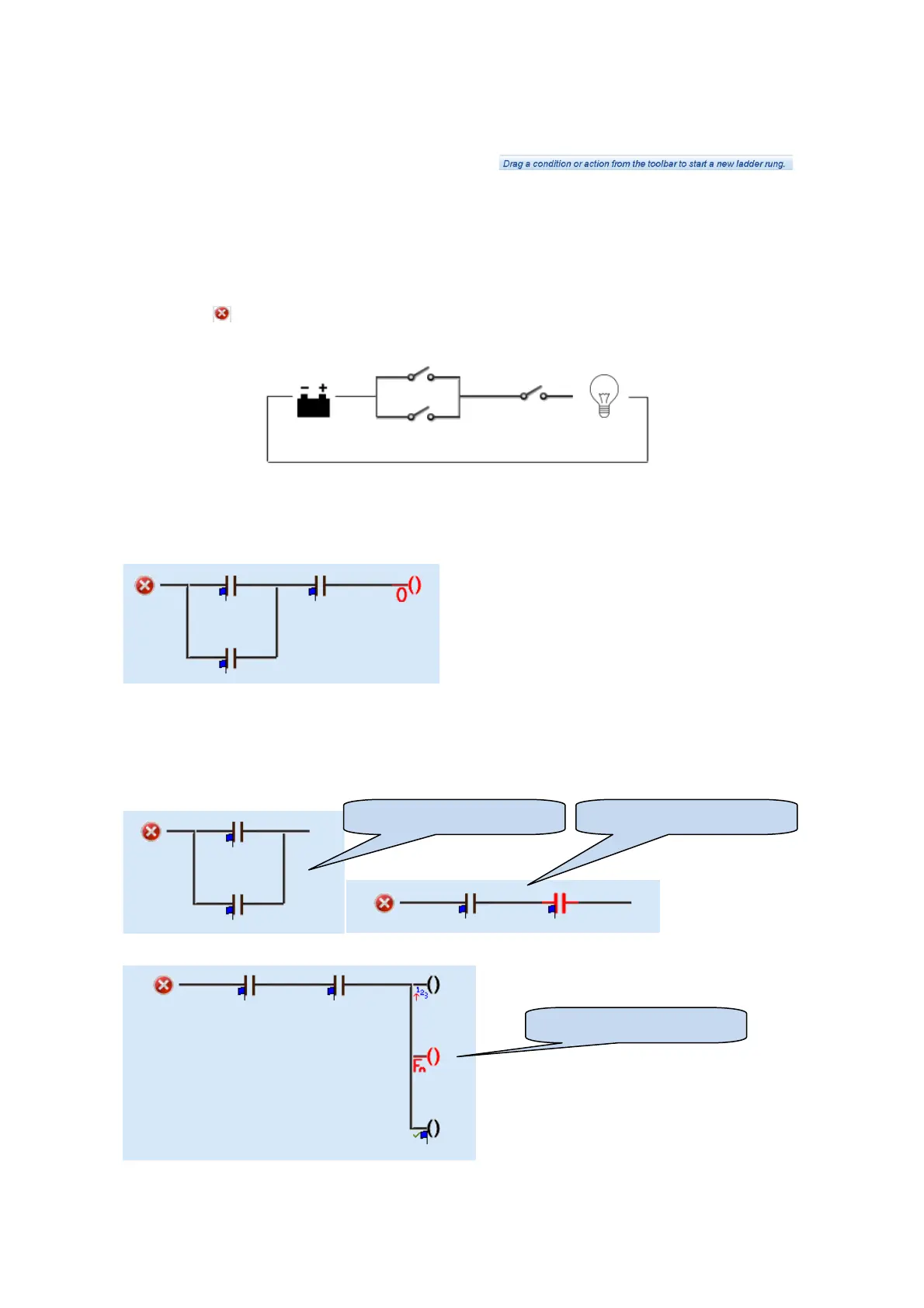
Imagine the schematic like a simple circuit with a battery and a bulb.
There are two switches (Output sources) in parallel to provide an OR function and one switch (Output source)
in series to provide an AND function.
When the conditions are satisfied, the bulb will illuminate (The action will occur).
An equivalent PLC ladder rung looks like this :
Rungs are processed in order (rung 1, rung 2, rung 3 etc). This sequence repeats every 100mS.
Careless setting of the PLC logic can cause toggling of an output at a rate of 100mS on/off. This may shorten
the life and/or cause damage to externally connected slave relays or other connected equipment.
Conditions can be placed in series to form an AND operation, or in parallel for form an OR operation:
Actions can be placed in parallel to perform multiple actions upon one condition:
PLC Logic OR Conditions PLC Logic AND Conditions
PLC Logic multiple actions