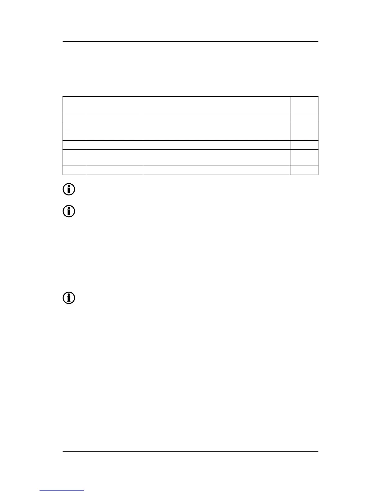
The table below contains the parameters to make the system ready for split phase measuring.
Below is an example with 240/120 V AC, which can be connected directly to the GPC's terminals without the
use of a voltage transformer. If a voltage transformer is necessary, the nominal values of the transformer
should be used instead.
Setting Adjustment Description Adjust to
value
6004 G nom. voltage Phase-neutral voltage of the generator 120 V AC
6041 G transformer Primary voltage of the G voltage transformer (if installed) 120 V AC
6042 G transformer Secondary voltage of the G voltage transformer (if installed) 120 V AC
6051 BB transformer set 1 Primary voltage of the BB voltage transformer (if installed) 120 V AC
6052 BB transformer set 1 Secondary voltage of the BB voltage transformer (if instal-
led)
120 V AC
6053 BB nom. voltage set 1 Phase-neutral voltage of the busbar 120 V AC
The measurement U
L3L1
shows 240 V AC. The voltage alarm set points refer to the nominal
voltage 120 V AC, and U
L3L1
does not activate any alarm.
The GPC has two sets of BB transformer settings, which can be enabled individually in this
measurement system.
3.8 Scaling
Default voltage scaling for the GPC-3 is set to 100 V-25000 V. To be able to handle applications above 25000
V and below 100 V, it is necessary to adjust the input range so it matches the actual value of the primary
voltage transformer. This makes it possible for the GPC-3 to support a wide range of voltage and power val-
ues.
Setup of the scaling can be done from the display by using the jump function or by using the USW.
When changing the voltage scaling in menu 9030, the unit will reset. If it is changed via the
USW, it is necessary to read the parameter again.
Scaling of nominal voltage and voltage read-out is done in menu 9030.
GPC-3 DRH 4189340587 UK Functional descriptions
DEIF A/S Page 15 of 122

 Loading...


